
A rigid-flex PCB combines rigid circuit board sections and flexible interconnects in one continuous structure. Components are mounted mainly on the rigid areas, while the flexible sections let different parts of the circuit fold into position, fit around mechanical features, or move in a controlled way.
This construction can replace separate rigid boards, cables, and connectors. That makes it useful in products where internal space, weight, assembly complexity, or connector reliability has become a real design constraint.
The trade-off is a more expensive and demanding bare board. Rigid-flex only earns that additional cost when it solves a problem that a conventional rigid-board assembly cannot solve as effectively.
Table of contents
- What a Rigid-Flex PCB Actually Is
- How a Rigid-Flex PCB Is Constructed
- Static Flex vs. Dynamic Flex in Rigid-Flex PCBs
- When a Rigid-Flex PCB Makes Sense
- Rigid-Flex PCB Advantages and Trade-Offs
- Common Rigid-Flex PCB Applications
- Basic Rigid-Flex PCB Design Considerations
- Manufacturing and Testing
- Frequently Asked Questions
- Final Considerations
What a Rigid-Flex PCB Actually Is
A rigid-flex PCB contains both rigid and flexible circuit regions that are manufactured as one interconnected board. Copper conductors run continuously between these regions, carrying signals and power without requiring a detachable cable at every connection.
The structure has three basic parts:
- Rigid sections support components, connectors, plated holes, and other features that require mechanical stability.
- Flexible sections allow the circuit to bend, fold, or pass through restricted spaces.
- Rigid-to-flex transition areas connect the two structures and must be protected from excessive mechanical stress.
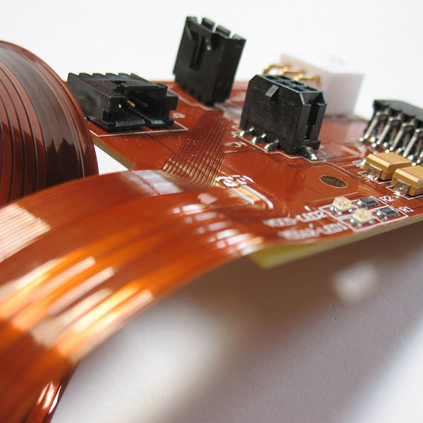
A simple rigid-flex board might have two rigid sections joined by one flexible section. One rigid area could hold the main processor and power circuitry, while the other supports a display or sensor. During assembly, the flexible section folds so both rigid areas fit into the enclosure at the required angles.
More complex designs may include several rigid sections, multiple flexible layers, controlled-impedance traces, blind vias, microvias, or shielding. Regardless of complexity, the same principle applies: the electrical connection is built into the board rather than added later as a separate cable-and-connector assembly.
Rigid PCB, Flex PCB, and Rigid-Flex PCB
A rigid PCB uses a mechanically stable substrate, commonly an FR-4 laminate. It provides a fixed platform for components and is the standard choice for most electronic products.
A flex PCB is built mainly from thin, bendable dielectric materials such as polyimide. It may be used as a cable replacement, wrapped around a mechanical feature, or installed in a moving part of a product. Some flex circuits have local stiffeners under component or connector areas, but adding a stiffener does not necessarily make them rigid-flex boards.
A rigid-flex PCB integrates permanent rigid and flexible regions into the same laminated circuit structure. It is not simply a rigid PCB connected to a detachable flex cable. This difference affects the stackup, material set, bend design, manufacturing process, assembly method, and cost model. A detailed comparison of rigid PCB, flex PCB, and rigid-flex PCB structures helps clarify when each architecture fits.
How a Rigid-Flex PCB Is Constructed
Most rigid-flex boards combine polyimide flexible layers with rigid laminate materials. Copper traces are formed on the flexible layers and continue into the rigid sections, where additional conductive and dielectric layers may be added.
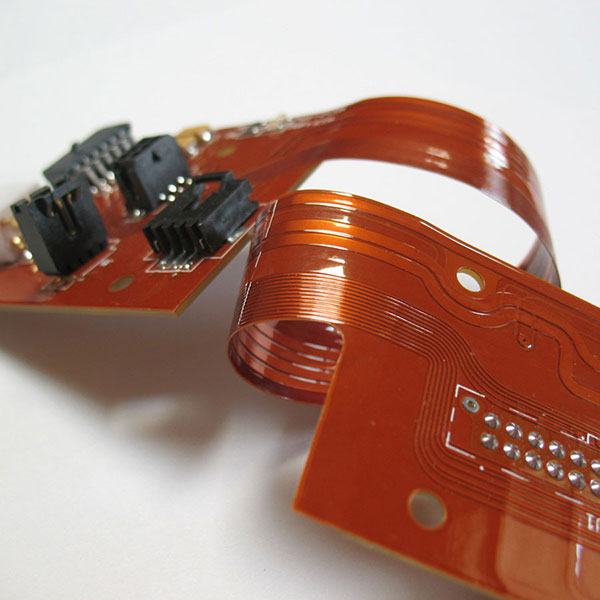
Polyimide film is commonly used as the flexible dielectric. It can tolerate bending and the temperatures involved in PCB fabrication and component assembly.
Copper foil forms the electrical conductors. Copper type, thickness, grain structure, and layout all affect bending performance. Rolled-annealed copper is often considered for applications involving repeated movement, but copper selection alone does not determine flex life.
Coverlay protects conductors in the flexible regions. It performs a role similar to solder mask on a rigid board but is made from a flexible insulating film and bonding material. Openings expose pads and other areas that require electrical contact.
Rigid laminates and prepreg form the stable component-supporting regions. Depending on the design, these sections may contain multilayer routing, planes, plated through-holes, blind vias, or microvias.
Some constructions also use stiffeners, shielding films, bonding films, pressure-sensitive adhesives, or local reinforcement. These features should be selected for a defined electrical, mechanical, or assembly need rather than added as general precautions.
The Rigid-to-Flex Transition
The rigid-to-flex transition is where the board changes from a thick, mechanically stable structure to a thin, flexible one. That sudden change in stiffness makes it a potential stress concentration area.
A common mistake is allowing the flexible section to bend sharply at the rigid edge. Repeated stress near that edge can damage copper traces or flexible materials even when the middle of the flex section remains intact.
The active bend should therefore begin at a controlled distance from the transition whenever the product structure allows it. Vias, component pads, abrupt trace changes, and other rigid features should also be kept away from areas that will flex.
The exact transition design depends on the stackup, bend geometry, materials, enclosure, and fabricator’s process. There is no single transition treatment that works for every rigid-flex board.
Static Flex vs. Dynamic Flex in Rigid-Flex PCBs
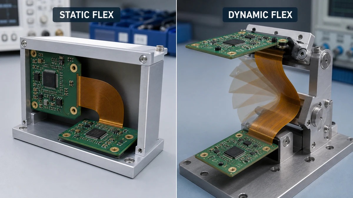
The first mechanical question in a rigid-flex project is whether the flexible section will bend only during assembly or continue moving while the product operates. This distinction affects the material selection, flex thickness, copper layout, bend radius, mechanical support, and validation plan.
Static Flex
A static-flex section is bent once or a limited number of times during assembly. After installation, it remains in a fixed position for most of the product’s service life.
Consider a compact instrument with a main control board and a display board installed at a right angle. A flexible section can connect the two rigid areas and fold into position when the assembly enters the enclosure. Once the housing is closed, the board no longer moves.
Static does not mean that bend geometry can be ignored. A flex section that is pulled tight, sharply creased, twisted, or pressed against an enclosure feature can still fail. The design must account for the installed radius, flex length, assembly sequence, and long-term mechanical strain.
Dynamic Flex
A dynamic-flex section bends repeatedly during normal operation. Possible examples include an instrument hinge, moving sensor head, printer mechanism, or robotic joint.
Dynamic requirements need to be defined in measurable terms. The design team should specify the expected bending cycles, bend radius, angle and direction, movement speed, twisting, operating temperature, and surrounding mechanical support.
Dynamic flex regions are usually kept thin and mechanically balanced. Copper traces should cross the bending area smoothly, without sharp corners or abrupt width changes. Vias, component pads, and plated holes should remain outside the active bend wherever possible.
Rolled-annealed copper may provide better fatigue performance than electrodeposited copper in demanding dynamic applications, but it is only one part of the solution. Copper thickness, total flex thickness, layer count, bend radius, trace orientation, coverlay, and operating conditions all affect service life.
A rigid-flex PCB should not be described as suitable for repeated movement unless its construction and test plan have been developed for that specific duty cycle.
When a Rigid-Flex PCB Makes Sense
Rigid-flex is most useful when the interconnection and mechanical packaging have become significant parts of the product problem.
It may be a good choice when:
- Several circuit sections must fit on different planes.
- Connectors and cable loops consume too much internal space.
- The product must be smaller or lighter.
- Cables are difficult to install consistently.
- The circuit must pass around a battery, display, sensor, motor, or other mechanical feature.
- Vibration or repeated handling creates risks at conventional connections.
- A defined section must bend during product operation.
- Reducing part count simplifies assembly and inspection.
A wearable monitor provides a simple example. Separate rigid areas may be needed for the sensor interface, processor, battery connection, and user controls. A rigid-flex PCB can position those areas around the enclosure while maintaining continuous electrical connections between them.
A rigid-flex PCB makes less sense when the product is flat, space is readily available, and standard rigid boards with proven connectors already meet the requirements. It can also be a poor fit for early prototypes whose mechanical architecture changes frequently.
The decision should be based on the complete assembly, not the bare-board price alone.
Rigid-Flex PCB Advantages and Trade-Offs
The most important rigid-flex PCB advantages are related to integration. However, each advantage depends on how the board is designed and used.
Fewer Connectors and Cables
Replacing a cable-and-connector interface with continuous copper removes several mechanical contact and termination points. This can reduce risks associated with loose connections, incomplete insertion, cable damage, contamination, or assembly mistakes.
It does not eliminate interconnection risk altogether. Stress can instead move into the flexible section or transition area. A poorly designed rigid-flex board may be less reliable than a well-designed conventional assembly.
Better Use of Internal Space
Flexible sections can fold between rigid areas and follow a three-dimensional product shape. This allows electronics to fit around batteries, displays, optics, motors, sensors, and structural features. Removing connector housings and cable loops may also release space for other components.
Lower Weight and Fewer Assembly Operations
Connectors, cables, housings, and strain-relief components add weight. Removing some of them can make the complete assembly lighter and reduce the number of parts that must be purchased, stored, installed, and inspected.
Rigid-flex assemblies still require careful handling. Unsupported flex regions can move during component placement or reflow, so process carriers, pallets, or temporary support may be needed.
Higher Bare-Board Cost
A rigid-flex bare board generally costs more than a conventional rigid PCB. It uses specialized materials and requires additional control over lamination, layer registration, coverlay, routing, and handling. Long or irregular flex sections may also reduce material utilization on the manufacturing panel.
More Design and Manufacturing Constraints
Rigid-flex requires coordination between electrical layout and mechanical movement. The designer must account for bend locations, flex length, transition areas, copper distribution, coverlay openings, stiffeners, assembly clearances, and the final folded shape.
The pool of suitable suppliers may also be smaller than it is for standard rigid PCBs. The process of evaluating a rigid-flex PCB manufacturer should compare the proposed materials, stackup, dimensions, and reliability requirements—not simply whether rigid-flex appears on its capability list.
System Cost Can Differ from Bare-Board Cost
It is misleading to compare only a rigid-flex PCB with one rigid PCB. The alternative may include several rigid boards, cables, connectors, fixtures, assembly operations, and inspection steps.
Rigid-flex may still cost more at the system level, but the difference should be calculated rather than assumed.
Common Rigid-Flex PCB Applications
Medical Devices
Wearable monitors, hearing devices, portable diagnostic equipment, imaging probes, and compact therapeutic devices may use rigid-flex constructions. In a handheld ultrasound probe, for example, rigid sections can support processing, sensing, and interface circuitry in different parts of the housing.
Medical electronics may also require controlled materials, process records, traceability, and formal change management. When manufacturing operates under an ISO 13485 quality management system, these controls can become part of the PCB and assembly documentation. They are separate from the electrical benefits of using rigid-flex. For production support, review Sugamed’s flex and rigid-flex PCB fabrication capabilities.
Aerospace and Defense Electronics
Aerospace systems often have strict space and weight limits. Reducing connector count and fitting electronics into complex enclosures can make rigid-flex valuable in avionics, communication modules, sensors, and other compact assemblies.
Consumer and Wearable Electronics
Smartwatches, wireless earphones, cameras, foldable devices, and AR or VR equipment often contain several circuit areas inside a small enclosure. If the board crosses a working hinge, the flex section must be designed as a dynamic circuit rather than merely folded into place during assembly.
Automotive Electronics
Camera modules, lighting systems, sensors, control interfaces, and infotainment hardware may use rigid-flex boards where space is restricted or circuit sections must be positioned at different angles. Temperature, vibration, moisture, and service-life requirements must be included in the material selection and validation plan.
Industrial Equipment and Robotics
Rigid-flex can be used in encoders, compact instruments, industrial sensors, and robotic mechanisms. In a moving assembly, the enclosure or cable guide should control where the flex section bends. Uncontrolled twisting, abrasion, or bending at the rigid edge can shorten its life even when the PCB was fabricated correctly.
Basic Rigid-Flex PCB Design Considerations
Define the Mechanical Requirement
The rigid-flex PCB design process should begin with a brief that identifies static or dynamic operation, bend position and direction, minimum bend radius, bend angle, expected flex cycles, available flex length, final installed shape, and operating environment.
The mechanical path should be reviewed using an enclosure model or physical mock-up when possible. This is more reliable than estimating the required flex length from a flat PCB outline.
Keep Critical Features Outside the Bend
Components, vias, plated holes, and connector pads should normally remain outside the active bend. These features increase local stiffness and may concentrate stress. The required separation depends on the stackup and bend geometry and should be confirmed with the fabricator.
Route Traces for Bending
Traces should pass through the bend smoothly. Sharp corners, abrupt width changes, and irregular copper distribution can create stress concentration points. In dynamic areas, traces generally cross the bending axis rather than following it.
Coordinate the Stackup Early
The rigid-flex PCB stackup should be developed with the intended manufacturer before the layout is finalized. Important items include layer counts, available materials, copper type and thickness, flex dielectric thickness, coverlay, finished thicknesses, controlled impedance, via structures, and transition design.
A design may be theoretically manufacturable but poorly matched to a stable production process. Early review reduces the risk of redesign after the Gerber files are complete.
Manufacturing and Testing
Rigid-flex PCB manufacturing combines flexible-circuit processing with multilayer rigid-board fabrication. The flexible circuit layers are formed first, and coverlay is applied where conductor protection is required. The flex layers are then aligned with rigid laminate materials and incorporated into the combined structure.
Manufacturing control is particularly important for flexible-material movement, registration between rigid and flexible layers, resin flow around transitions, coverlay alignment, drilling through mixed materials, and protection of exposed flex regions.
Electrical testing verifies continuity and isolation, but it cannot prove that the circuit will survive its mechanical duty. Depending on the application, validation may also include visual and dimensional inspection, cross-section analysis, testing in the final folded condition, repeated flex-cycle testing, thermal cycling, vibration, or mechanical shock.
Dynamic testing should reproduce the intended bend radius, angle, speed, and movement direction. Manually bending a sample several times is not a meaningful substitute for a defined cycle test.
Frequently Asked Questions
Can a rigid-flex PCB bend repeatedly?
Yes, but only if it is designed for dynamic flexing. Many rigid-flex boards are intended to bend only during assembly. Repeated movement requires a suitable stackup, copper layout, bend radius, mechanical path, and validation plan.
What are the main advantages of rigid-flex PCBs?
The main advantages include fewer connectors, more efficient use of internal space, lower assembly weight, reduced part count, and the ability to position circuit sections on different planes.
Are rigid-flex PCBs more reliable?
They can reduce risks associated with connectors and cable assemblies. However, they also introduce mechanical risks in the bend and transition areas. Reliability depends on the materials, layout, fabrication, assembly, enclosure, and operating conditions.
Are rigid-flex PCBs more expensive?
The bare board is generally more expensive than a conventional rigid PCB. The complete assembly cost may be closer when the comparison includes connectors, cables, assembly operations, testing, enclosure space, and failure risk.
What materials are used in rigid-flex PCBs?
Common materials include polyimide flexible laminates, copper foil, coverlay, bonding films, FR-4 or other rigid laminates, and prepreg. Stiffeners and shielding materials may be added where required.
How should I choose between rigid-flex and separate boards with cables?
Start with space, movement, connector count, assembly requirements, operating environment, production volume, serviceability, and total system cost. If a conventional assembly meets these requirements without creating packaging or reliability problems, rigid-flex may add unnecessary complexity.
Final Considerations
Rigid-flex is not simply a more advanced version of a rigid PCB. It is a different way of designing the electrical and mechanical structure of a product.
It earns its cost when connectors and cables create a genuine problem—too much space, too much weight, difficult assembly, uncontrolled movement, or unacceptable reliability risk. It is less convincing when a standard rigid-board assembly already performs well.
Before committing to rigid-flex, define the installed shape, bend radius, movement type, expected flex cycles, operating environment, and service requirements. Then review the proposed stackup and transition structure with the manufacturer before the layout is finalized.