Infusion Pump PCBA Medical-Grade PCB Assembly for Every Pump Architecture
Home » Therapeutic Device PCBA » Infusion Pump PCBA
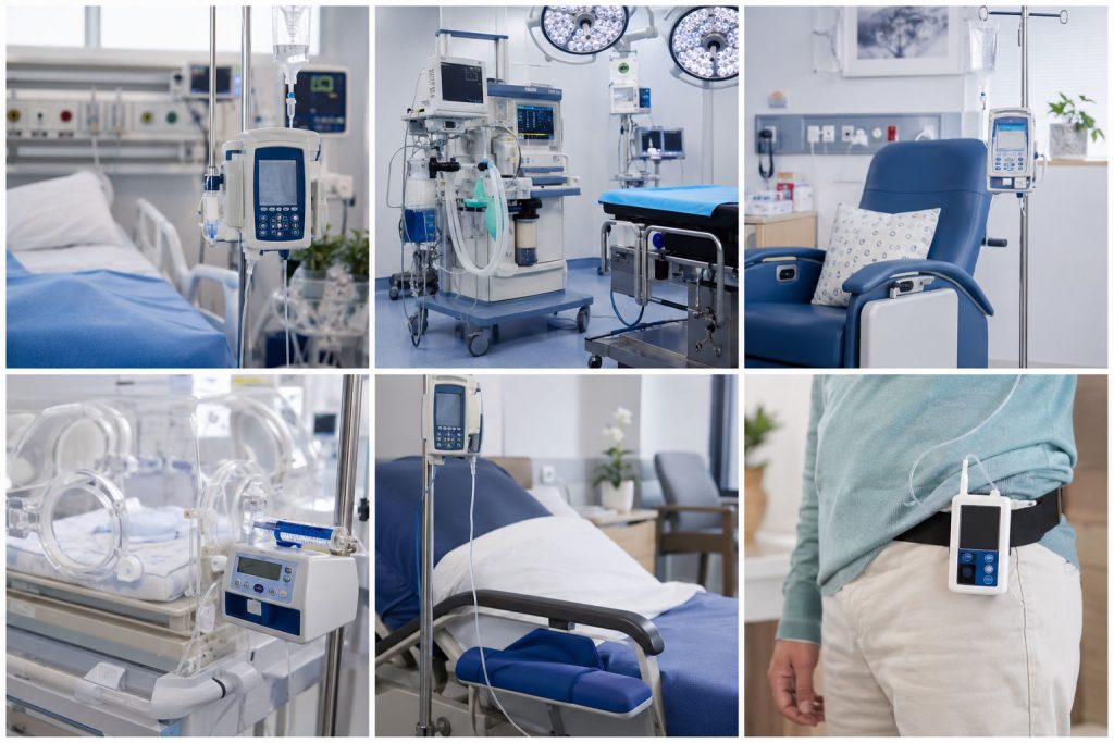
Reliable, traceable PCBA build services purpose-engineered for infusion pumps — supporting precision dosing, patient safety, and global regulatory submissions.
What Is an Infusion Pump PCBA?
An infusion pump delivers fluids — medications, nutrients, or blood products — into a patient’s body at a precisely controlled rate and dose. Behind that precision sits a tightly integrated electronic system, where every PCBA must behave deterministically, fail safely, and remain traceable across its entire lifecycle.
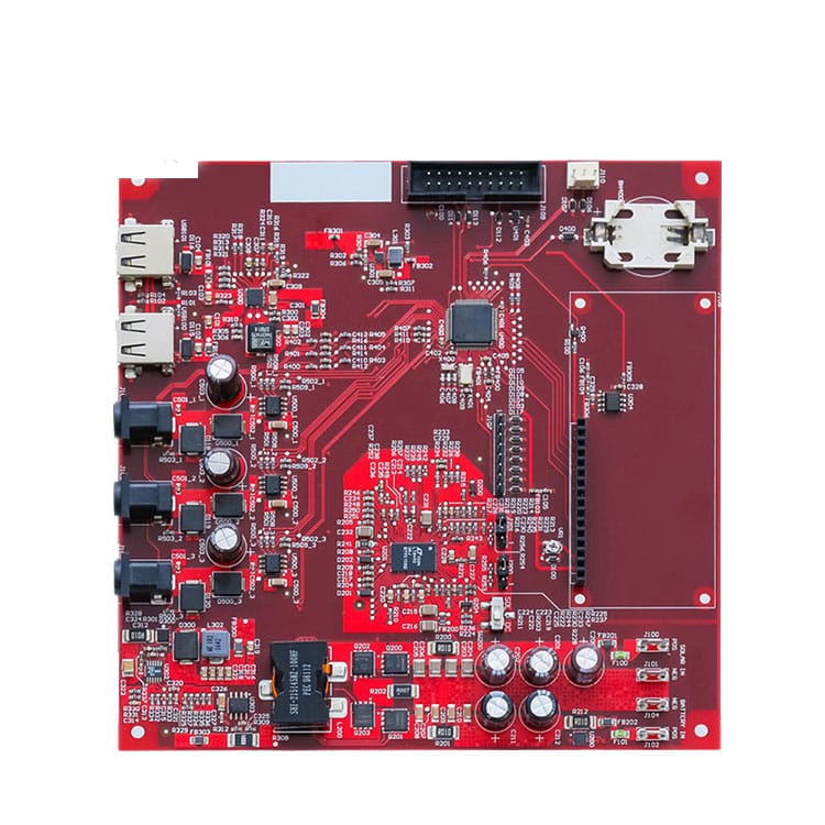
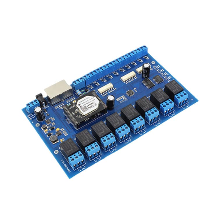
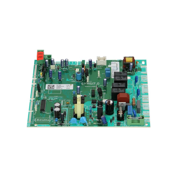
A typical infusion pump PCBA stack includes a main control board running the dosing algorithm and safety logic, a motor driver board that converts digital commands into accurate mechanical motion, a sensor interface board for occlusion, air-in-line and flow detection, a medical-grade power and battery management board, and a human-machine interface board that drives the display, keypad, and alarm system. Together, they form a safety-critical, real-time system that must comply with global medical device regulations from day one of development.
PCBA Solutions by Pump Type
Volumetric Infusion Pump
Full PCBA stack — main control, motor driver, sensor interface, power, HMI, connectivity. Build focus: long-run flow consistency, low-flow occlusion detection, smart-pump network integration.
Syringe Pump
Compact, high-precision, low-noise. Tighter tolerances on motor driver assembly and signal integrity. NICU-grade builds verified against drug delivery waveform, not just average flow rate.
PCA Pump
Heaviest regulatory scrutiny in the category. PCBA build supports dual-path patient demand verification and hardware bolus-ceiling circuits as designed, with audit log written to NV storage verified through DVT.
Ambulatory / Wearable Pump
High-density HDI boards with low-power SoM, discrete BMS, and BLE modules. Test profiles include mechanical shock and vibration that hospital pumps never see.
Different Clinical Settings, Different PCBA Constraints
“Infusion pump PCBA” is not one design problem — it’s six, and each clinical setting drives different requirements down to the board level.
| Clinical Setting | Typical Device | What the PCBA Has to Handle |
| ICU / Critical Care | Volumetric, syringe pump | 24/7 uptime, multi-alarm redundancy, nurse station connectivity |
| OR / Anesthesia | Syringe pump | Near-zero flow pulsation, dense RF environment |
| Oncology Ward | Volumetric, PCA pump | Cumulative dose tracking, infusion history logging |
| NICU | Syringe pump | Sub-microliter accuracy, ultra-low motor noise |
| Post-Op Pain Mgmt | PCA pump | Patient-controlled logic, tamper-proof audit trail |
| Home Care / Ambulatory | Wearable pump | Battery life, BLE telemetry, drop tolerance |
Engineering Challenges
Recurring Build-Side Issues — and How We Address Them
Dosing Accuracy at the Board Level
The ±2–5% system spec is an error-budget problem, not a single-board problem. Motor step resolution, ADC quantization, sensor drift, and temperature effects all accumulate. Our DFM review maps every build-side contributor and flags where margin is thin before prototype — rather than discovering the stack-up issue during DVT.
Alarm Reliability Under Single-Fault Conditions
IEC 60601-1 requires the alarm function to survive any single fault. The alarm circuit can’t share a power rail, ground path, or control signal with the function it monitors — these constraints must be resolved in the schematic. We support build and verification of dual-MCU, watchdog, and cross-monitoring topologies, with boundary-scan and ICT options to confirm safety-critical nets before functional test.
EMC in Real Clinical Environments
ICU and OR RF environments are dense — electrosurgical units, wireless monitors, defibrillators. We address motor driver switching noise, sensor trace routing, and wireless module placement during DFM, building margin beyond the IEC 60601-1-2 pass threshold. Passing the test and performing well in clinical use are not always the same thing.
Power Continuity During Battery Switchover
The 50–200ms reset risk during AC-to-battery handoff is real and often missed until full-system testing. We include calibrated switchover testing as a standard DVT case on every infusion pump program — testing the actual load profile of the full board assembly, not estimates from spec sheets.
Miniaturization for Wearable Designs
High-density HDI layouts introduce thermal and signal integrity challenges that don’t appear in lower-density designs. HDI stackup selection, via-in-pad for fine-pitch components, and thermal relief management all need explicit attention during layout review — before prototype build, not after.
Compliance & Quality
By the time you reach production, the decisions that determine whether you pass IEC 60601-1 have already been made. We work compliance into three stages.
Stage 01: At Design Review
Small rigid boards, usually four layers, with an OLED driver and an ultra-low-power MCU. Coin-cell powered in most cases. Volume-friendly, and the segment where manufacturing cost discipline matters most.
Stage 02: At Manufacturing
Dedicated IPC-A-610 Class 3 line — not shared with consumer or industrial programs. 100% inline AOI, selective or 100% X-Ray, ICT fixtures designed to ≥98% coverage. Lot-level traceability on every board, retained per applicable regulatory requirements.
Stage 03: At Documentation
Manufacturing-side records — DHF inputs, process validation reports, traceability files, EMC and safety pre-compliance data — formatted for FDA 510(k), EU MDR, and NMPA submissions. Your regulatory team won't have to chase us for evidence.
| Process Control | Standard | Our Approach |
|---|---|---|
| Assembly Quality | IPC-A-610 Class 3 | Dedicated Class 3 line, not shared with consumer/industrial |
| Optical Inspection | — | 100% inline AOI on every board |
| X-Ray | — | Selective or 100% based on BGA/QFN density |
| In-Circuit Test | — | ICT fixtures designed to ≥98% coverage target |
| Traceability | — | Lot-level forward and backward, retained per applicable regulatory requirements |
FAQ
What certifications does infusion pump PCBA manufacturing require?
ISO 13485 quality system, IPC-A-610 Class 3 workmanship, and IEC 60601-1 / -1-2 / -1-6 / -1-8 compliance at the device level. Software components typically follow IEC 62304 Class B or C. The specific combination depends on the regulatory markets you’re targeting.
What's a realistic prototype lead time?
2–3 weeks for standard designs, 4–6 weeks for complex multilayer boards or designs with long-lead medical-grade components. Lead time is mostly driven by component sourcing, not assembly. Schedule is committed after DFM review — not before.
Can you handle low-volume prototype builds? Is there an MOQ?
Yes. We routinely build 5–50 units on the same SMT line and inspection equipment as mass production, so EVT/DVT data is representative of eventual production. There is no formal MOQ for prototype stages.
How does component traceability work for FDA audits?
Every board carries a serialized record mapping it to the exact component lots used in assembly, retained per applicable regulatory requirements. CAPA tracing is pulled from the manufacturing database — forward and backward — not manually assembled from spreadsheets.
Do you provide functional testing and burn-in?
Yes. Turnkey service covers sourcing, SMT, through-hole, conformal coating, functional test, and burn-in. Custom test fixtures and ATE programs are designed in-house. Burn-in protocols are defined during DVT based on the device’s failure mode profile.
What's the difference between syringe pump and volumetric pump PCBA?
Different drive mechanisms — linear lead screw vs. peristaltic — different motor driver architectures, and different accuracy budgets. Syringe pump tolerance requirements are generally tighter. Some platforms share a control board across both with configuration differences; others don’t.
Can you support firmware development alongside hardware?
We treat hardware PCBA and embedded firmware as separate but coordinated work streams. We align test fixtures and bring-up procedures to your firmware build. Firmware development support is scoped per project — not bundled by default.
How do you handle EMC for pumps going into ICU or OR?
EMC for IEC 60601-1-2 is part of the DFM review process. We address PCB-level layout, motor driver switching noise, and wireless module antenna placement during design review — before prototype. This builds margin beyond the compliance pass threshold, not just enough to pass.