
A rigid-flex PCB stackup is not a rigid multilayer board with a flexible tail added afterward. The flex circuit is part of the layer structure from the beginning, so its position affects lamination balance, total thickness, routing references, and the way the board leaves each rigid section. The useful starting point is therefore the flex substack: determine what must continue through the bend area, then build the rigid portions around it.
Table of contents
- Define the Flex Substack Before Adding Rigid Layers
- Place the Flex Layers Where the Stack Can Stay Balanced
- Account for Coverlay and Bonding Materials in the Real Thickness
- Balance Copper Without Treating Every Layer the Same
- Choose Layer Count by Function, Not by a Standard Example
- Review the Stackup as an Electrical, Mechanical, and Manufacturing Structure
Define the Flex Substack Before Adding Rigid Layers
The layers that pass continuously through the flexible area form the flex substack. They may carry signals, power, reference copper, or a combination of these functions. Once their number and function are established, additional rigid-only layers can be added above and below them where components, dense routing, or local plane structures are required.
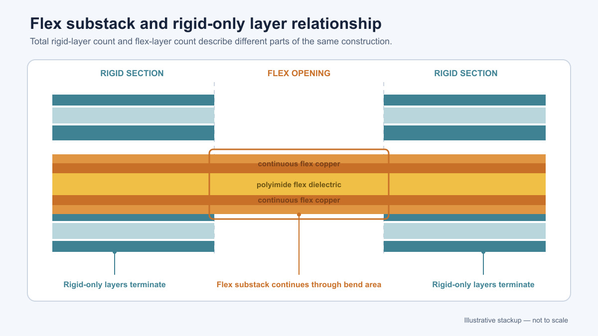
This distinction prevents a common planning mistake: choosing a total layer count first and then trying to place the flex layers wherever space remains. A six-layer rigid section, for example, does not tell you whether two, four, or all six layers continue through the flex area. Those are different constructions with different thickness, bend behavior, bonding requirements, and routing capacity.
The total layer count describes the rigid section, but the flex-layer count determines what actually bends. Both numbers need to be shown clearly on the stackup drawing.
The rigid and flex regions therefore overlap rather than operate as two independent boards. In the rigid areas, cores, prepregs, and outer copper build around the flex substack. At the transition, the rigid-only materials terminate while the flex layers continue into the bend area.
Place the Flex Layers Where the Stack Can Stay Balanced
For many constructions, placing the flex substack near the center of the rigid buildup is the most straightforward way to keep the layer sequence and material thickness reasonably symmetric. Equal or closely matched buildup above and below the centerline reduces the difference in lamination stress across the panel.
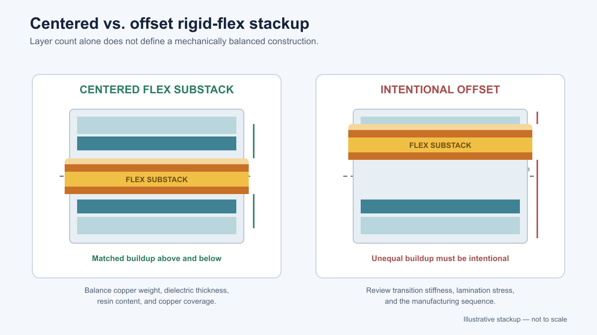
Symmetry is broader than simply counting layers. Copper weight, dielectric thickness, resin content, and large differences in copper coverage can all make a nominally symmetric stack behave unevenly during pressing. A drawing that shows three layers above and three below the flex core may still be poorly balanced if one side contains much heavier copper or a substantially different dielectric structure.
Off-center flex placement can be necessary. Component-height restrictions, impedance references, blind-via sequencing, or a required connection geometry may force the flex layers away from the center. In that case, the asymmetry should be intentional and reviewed as part of the actual manufacturing stack—not treated as a harmless change in layer numbering.
The same placement decision also affects the rigid-to-flex transition. If more material terminates on one side of the flex substack than the other, the transition can experience uneven stiffness. That does not automatically make the design unusable, but it changes what must be controlled in the transition geometry and lamination plan.
Account for Coverlay and Bonding Materials in the Real Thickness
The flex portion is not made from copper and polyimide alone. Coverlay protects the flex copper in exposed flexible areas, while adhesive films, bondply, or controlled-flow bonding materials join flex layers and connect the flex substack to the rigid buildup. Each of these materials contributes thickness and affects how resin behaves near the flex opening.
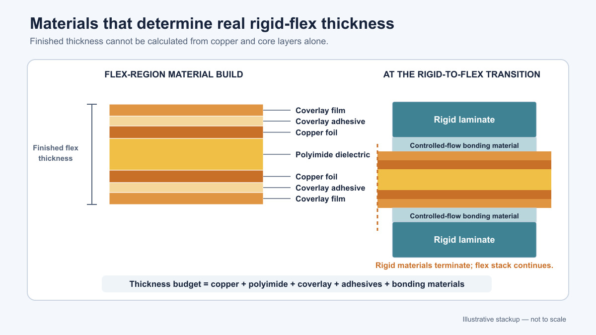
Coverlay performs a role similar to solder mask, but it is laminated as a film and must remain compatible with bending. Its adhesive and film thickness belong in the flex construction, especially when the bend radius or connector height is sensitive to the finished thickness.
Bonding material at the rigid-to-flex interface needs enough flow to fill and bond the rigid buildup without flooding the area intended to remain flexible. The exact material system and lamination method vary by construction. “No-flow prepreg” is often used as a general label, but the important engineering requirement is controlled resin flow at the rigid boundary, not the use of one universal product or process.
Stackup drawings should therefore show the complete build, including coverlay, adhesive layers, cores, prepregs, and copper—not only the conductive layers. Otherwise, the nominal finished thickness may omit the very materials that determine whether the flex section fits the mechanical envelope.
Balance Copper Without Treating Every Layer the Same
Copper distribution influences pressing and thickness uniformity, but balance does not mean making every layer electrically identical. Signal layers, planes, and local copper features serve different purposes. The goal is to avoid extreme, unnecessary differences in copper coverage that make resin filling and dimensional control harder.
Large solid areas on one layer beside very sparse copper on the opposing layer can create different resin demand across the stack. Fabricators may recommend non-functional copper features or changes to panel-level copper distribution when the imbalance is severe. Those adjustments need to preserve clearances, impedance structures, and flex behavior rather than being added automatically.
Copper in the bend area deserves separate attention. More conductive layers, heavier copper, and thicker dielectric buildup all increase the flex-section thickness and change its bending strain. A rigid section may benefit from added planes or routing layers, while the flex section may not need—or should not carry—the same layer count. This is another reason to separate the rigid-layer requirement from the flex-layer requirement early.
Choose Layer Count by Function, Not by a Standard Example
Layer-count examples are useful only when the function of the flex section is clear. A two-layer flex substack may be sufficient when the flexible region is primarily an interconnect between rigid sections. A larger flex substack may be needed when reference planes, controlled-impedance signals, shielding, or additional power paths must continue through the bend area.
The rigid sections can contain more layers than the flex section. A design may need extra rigid-only layers for component escape routing, power distribution, or local high-density interconnect while keeping the bend area comparatively thin. That arrangement is often more practical than carrying every rigid-layer function through the flex region.
As the construction becomes more complex, layer count also interacts with via type and lamination sequence. Blind or buried vias may require intermediate drilling and plating before the full rigid-flex stack is completed. The difficulty comes from the specific combination of flex-layer placement, via structure, material sequence, and registration—not from reaching a particular total layer number by itself.
Questions the stackup drawing should answer
- Which copper layers continue through each flex region?
- Which layers exist only inside the rigid sections?
- Where is the flex substack positioned relative to the rigid centerline?
- What materials form each rigid-to-flex bond?
- What is the finished thickness in the rigid and flex areas?
- Which vias require a separate drilling or lamination stage?
- Which layers provide the reference planes for signals that cross the transition?
These answers are more useful than selecting a generic “four-layer” or “eight-layer” example from a catalog. The final construction should be reviewed against the fabricator’s actual material set and process sequence before routing and mechanical dimensions depend on it.
Review the Stackup as an Electrical, Mechanical, and Manufacturing Structure
A workable rigid-flex stackup has to satisfy three views at the same time. Electrically, it must provide suitable routing and reference structures. Mechanically, the flex section must remain thin enough and be positioned appropriately for the required bend. From a manufacturing perspective, the material sequence, copper distribution, resin flow, via plan, and lamination order must form a buildable panel.
That review is most useful while the stackup is still adjustable. Once component placement, impedance geometry, enclosure height, and bend locations are tied to a particular construction, changing the flex-layer position can affect much more than the layer drawing.