
Through-Hole PCB Assembly Services
SugaMed provides through-hole PCB assembly services for medical electronics, supporting the assembly of connectors, relays, transformers, terminal blocks, and other leaded components. We also support mixed SMT and through-hole assembly on the same PCBA.
Core Capabilities
- 10 automatic through-hole insertion machines
- Mixed SMT and through-hole PCB assembly
- Wave soldering
- Through-hole reflow soldering for suitable components (Pin-in-Paste / PiP)
- Prototype, NPI, low-volume, and repeat production
- Assembly and inspection based on approved project requirements and applicable IPC-A-610 acceptance criteria
For Leaded Components and Applications Requiring Mechanical Support
Through-hole assembly involves inserting leaded electronic components into plated through-holes in a PCB and soldering them on the opposite side of the board.
Although SMT is the primary PCB assembly technology used in modern electronics, not every component is suitable for surface mounting. Through-hole assembly remains common for larger components, components designed with leads, and components that must withstand repeated insertion and removal or mechanical stress.
Typical through-hole components include:
- Connectors and pin headers
- Terminal blocks
- Transformers
- Relays
- Switches
- Large electrolytic capacitors
- Selected power components
- Large or irregularly shaped components
The decision to use through-hole assembly should be based on the component package, PCB design, mechanical requirements, and planned soldering process.
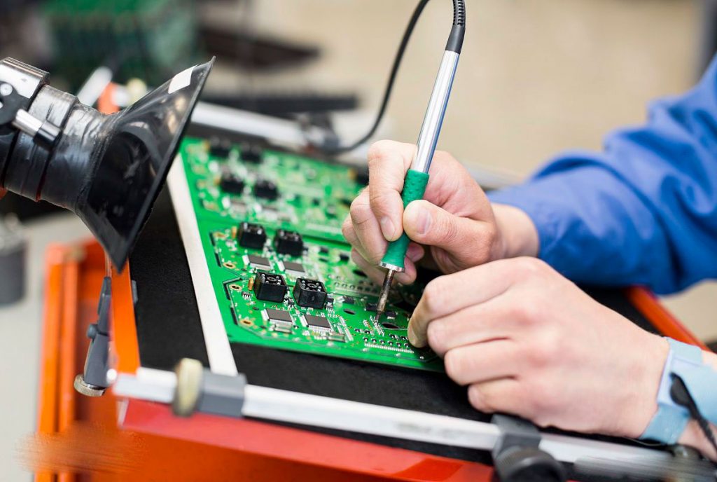
Our Through-Hole PCB Assembly Capabilities
SugaMed supports PCB assembly projects built primarily around through-hole components, as well as the more common mixed SMT and THT assembly approach.
10 automatic through-hole insertion machines
Mixed SMT and through-hole PCB assembly
Wave soldering
Through-hole reflow soldering for suitable components (Pin-in-Paste / PiP)
Prototype, NPI, low-volume, and repeat production
Assembly and inspection based on approved project requirements and applicable
| Capability | SugaMed Support |
|---|---|
| Assembly types | Through-hole assembly; mixed SMT + THT assembly |
| Automatic insertion | 10 automatic through-hole insertion machines |
| SMT production | 15 Fuji and Yamaha SMT production lines |
| Soldering process | Wave soldering |
| Through-hole reflow | Pin-in-Paste / PiP for suitable components |
| Production stages | Prototypes, NPI, low-volume, and repeat production |
| Inspection requirements | Based on the components, assembly structure, and approved project requirements |
| Testing | PCB-level ICT, programming, functional testing, ATE, and other tests based on project requirements |
| Traceability | Batch-, component-, and serial-level traceability available based on project requirements |
Assembly types
SugaMed Support
Through-hole assembly; mixed SMT + THT assembly
Automatic insertion
SugaMed Support
10 automatic through-hole insertion machines
SMT production
SugaMed Support
15 Fuji and Yamaha SMT production lines
Soldering process
SugaMed Support
Wave soldering
Through-hole reflow
SugaMed Support
Pin-in-Paste / PiP for suitable components
Production stages
SugaMed Support
Prototypes, NPI, low-volume, and repeat production
Inspection requirements
SugaMed Support
Based on the components, assembly structure, and approved project requirements
Testing
SugaMed Support
PCB-level ICT, programming, functional testing, ATE, and other tests based on project requirements
Traceability
SugaMed Support
Batch-, component-, and serial-level traceability available based on project requirements
For projects containing both SMT and through-hole components, our engineering team reviews the component mix, PCB layout, and manufacturing documentation before production to determine the appropriate assembly and soldering processes.
Mixed SMT and Through-Hole PCB Assembly
Modern PCB assemblies typically use more than one assembly technology.
Components such as ICs, resistors, capacitors, BGAs, and QFNs are generally assembled using SMT, while connectors, relays, transformers, terminal blocks, and some larger power components may be installed using through-hole technology.
A typical mixed-technology PCBA process may include:
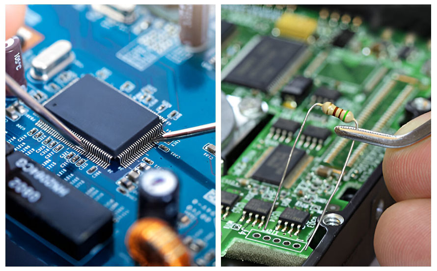
The exact production sequence is not fixed. It is adjusted based on the component distribution on both sides of the PCB, the types of through-hole components, the soldering method, and the testing requirements.
Having one manufacturer handle both SMT and through-hole assembly can also reduce the need to transfer partially assembled boards between suppliers and help maintain process consistency from NPI through ongoing production.
Through-Hole PCB Assembly Process
The production process varies from one PCBA to another, but through-hole assembly typically includes the following stages.
Engineering and Manufacturing Documentation Review
Before production, the PCB data, component information, and assembly requirements must be confirmed.
Common documents include:
- Gerber files
- BOM
- Assembly drawings
- Pick-and-Place files for SMT components
- Component polarity and orientation requirements
- Programming files
- Inspection and testing requirements
- Special process requirements
For through-hole components, the engineering review also considers lead dimensions, finished hole sizes, component orientation, mechanical clearances, and compatibility with the planned soldering process.
For example, a mismatch between connector lead dimensions and finished hole sizes can affect both component insertion and subsequent soldering quality.
Component Preparation and Insertion
Materials are checked against the approved BOM before entering the assembly process.
Components suitable for automatic insertion can be processed using automatic insertion equipment. Other components are assembled using an appropriate controlled process based on their package structure and project requirements.
Particular attention is paid to:
- Polarity of polarized components
- Connector orientation
- Component height
- Whether components sit properly against the PCB
- Mechanical interference between large components
Identifying insertion issues before soldering is generally easier to control than repairing them after soldering has been completed.
Through-Hole Soldering
After component insertion, the appropriate soldering process is selected based on the PCB layout and component types.
Wave Soldering
For PCBAs with multiple through-hole solder joints suitable for wave soldering, wave soldering can be used to solder multiple joints in a single process.
Process design must consider:
- Component layout on the solder side
- Spacing between components and pads
- Lead protrusion length
- Heat-sensitive components
- PCB structure and thermal mass
Not every PCB containing through-hole components is suitable for the same wave soldering parameters. Actual process conditions must be determined based on the specific design.
Through-Hole Reflow Soldering (Pin-in-Paste / PiP)
Through-hole reflow soldering, also known as Pin-in-Paste (PiP), may be used for through-hole components with suitable package structures and temperature ratings.
This process typically involves depositing the required amount of solder paste onto the through-hole pads during stencil printing. The through-hole components are then inserted before the assembly enters the reflow oven together with the SMT components.
The suitability of Pin-in-Paste depends on several factors, including:
- Whether the component can withstand reflow temperatures
- Finished hole size and lead dimensions
- Stencil design
- Required solder paste volume
- Solder joint fill requirements
PiP should therefore be selected after engineering evaluation rather than treated as a universal soldering method for all through-hole components.
Inspection
After soldering, the component installation and solder joint condition are inspected.
Common inspection items include:
- Missing or incorrect components
- Correct polarity and orientation
- Solder wetting
- Through-hole fill
- Insufficient solder
- Solder bridging
- Lead condition
- Component position
Acceptance is performed according to approved project requirements and applicable IPC-A-610 acceptance criteria.
PCB-Level Testing
If testing is required for the project, the assembled and inspected PCBA can undergo the specified tests.
Depending on the testing requirements provided or approved by the customer, testing may include:
- ICT
- Programming
- Functional testing
- ATE
- Burn-in testing or other project-specific tests
The test method should be determined based on the actual PCBA design and project requirements. Not every through-hole assembly project requires the same testing process.
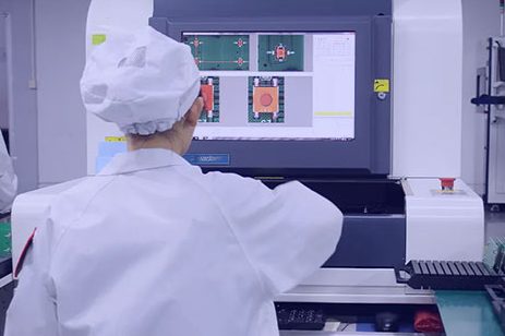
What to Check When Inspecting Through-Hole Solder Joints
Through-hole solder joints have different inspection priorities from SMT solder joints. Correct component placement does not necessarily mean that the solder joints meet all requirements.
Solder Wetting
The solder must wet the component leads and the PCB soldering surfaces properly. Contamination, insufficient heat, or other process issues can affect solder joint formation.
Through-Hole Fill
For plated through-hole connections, the amount of solder filling the hole is an important acceptance criterion.
The specific acceptance requirements should be determined according to the applicable IPC-A-610 class and approved project documentation rather than applying one fixed value to every product.
Solder Bridging and Insufficient Solder
Solder bridging between adjacent leads can cause short circuits, while insufficient solder can affect connection reliability.
These issues require particular attention on multi-pin components such as connectors and pin headers.
Component Orientation and Position
The orientation, position, and mechanical condition of connectors, polarized capacitors, relays, switches, and other components must also be checked against the assembly drawing and project requirements.
For medical electronics projects, any customer-specific workmanship, inspection, or testing requirements should be incorporated into the approved manufacturing documentation before production whenever possible.
What Is the Difference Between Through-Hole and SMT Assembly?
Through-hole and SMT assembly are not mutually exclusive choices. Modern PCBAs often use both technologies based on the package type and functional requirements of each component.
A medical PCBA may contain hundreds of SMT components while using only a small number of through-hole connectors, relays, or power components.
The key is to determine which installation method is appropriate for each component rather than deciding whether the entire PCB should use THT or SMT.
| Comparison | Through-Hole Assembly | SMT Assembly |
|---|---|---|
| Installation method | Component leads pass through plated holes in the PCB | Components are mounted directly on the PCB surface |
| Component density | Typically lower | Better suited to high-density layouts |
| PCB space | Requires through-holes | Makes compact layouts easier |
| Mechanical support | Suitable for selected leaded components requiring stronger mechanical support | Suitable for most modern electronic components |
| Automation level | Depends on the component and process | Generally highly automated |
| Common components | Connectors, relays, transformers, terminal blocks | ICs, resistors, capacitors, QFNs, and BGAs |
| Typical application | Usually used together with SMT | Primary assembly technology for modern PCBAs |
Installation method
Through-Hole Assembly
Component leads pass through plated holes in the PCB
SMT Assembly
Components are mounted directly on the PCB surface
Component density
Through-Hole Assembly
Typically lower
SMT Assembly
Better suited to high-density layouts
PCB space
Through-Hole Assembly
Requires through-holes
SMT Assembly
Makes compact layouts easier
Mechanical support
Through-Hole Assembly
Suitable for selected leaded components requiring stronger mechanical support
SMT Assembly
Suitable for most modern electronic components
Automation level
Through-Hole Assembly
Depends on the component and process
SMT Assembly
Generally highly automated
Common components
Through-Hole Assembly
Connectors, relays, transformers, terminal blocks
SMT Assembly
ICs, resistors, capacitors, QFNs, and BGAs
Typical application
Through-Hole Assembly
Usually used together with SMT
SMT Assembly
Primary assembly technology for modern PCBAs
Through-Hole Assembly in Medical Electronics
Through-hole components remain common in medical electronics PCBAs, particularly connectors, transformers, relays, terminal blocks, and selected power components.
These components may be used for board-to-board connections, external cable connections, power conversion, or mechanical switching. Their package structures and mechanical support requirements differ from those of standard SMT ICs.
In many projects, through-hole components are installed on the same PCBA as SMT components. For example, a control board may use SMT assembly for most ICs and passive components while using through-hole assembly for connectors or larger power components.
Whether through-hole technology is appropriate should be determined by the component specifications, PCB design, and product requirements. It should not be assumed solely because the product is a medical device.
Frequently Asked Questions
What is through-hole PCB assembly?
Through-hole PCB assembly is the process of inserting leaded electronic components into plated through-holes in a PCB and soldering them on the opposite side of the board.
Connectors, relays, transformers, terminal blocks, and some large or specialized components are still frequently assembled this way.
Can SMT and through-hole components be installed on the same PCB?
Yes.
Mixed SMT and THT assembly is a common PCBA configuration. ICs, passive components, BGAs, and QFNs are typically assembled using SMT, while connectors, transformers, relays, and other components may be installed using through-hole technology depending on the design.
The exact production sequence depends on the PCB layout and component mix.
Which components are commonly assembled using through-hole technology?
Common through-hole components include connectors, pin headers, terminal blocks, relays, transformers, switches, large electrolytic capacitors, and selected power components.
The final assembly method should be determined based on the component package, mechanical requirements, and PCB design.
Which soldering methods can be used for through-hole PCB assembly?
SugaMed supports wave soldering and through-hole reflow soldering (Pin-in-Paste / PiP) for suitable components and PCB designs.
The specific soldering process must be evaluated based on the PCB layout, component packages, and manufacturing requirements.
Is through-hole assembly suitable for prototypes and low-volume production?
Yes.
Through-hole assembly and mixed SMT + THT assembly can both be used for prototypes, NPI, low-volume production, and subsequent repeat production. The specific process depends on the PCB design and component mix.
Does medical PCB assembly always require IPC Class 3?
No.
The required IPC class depends on the product’s intended use, reliability requirements, risk assessment, and contractual requirements.
Some medical electronics products can be manufactured to IPC Class 2 acceptance criteria, while projects with higher reliability requirements may specify Class 3. The required class should be clearly defined in the approved project documentation.
What documents are typically required for a through-hole PCB assembly quote?
Gerber files, a BOM, and assembly drawings are typically recommended.
If the PCBA also includes SMT components, Pick-and-Place files should also be provided. Programming, inspection, and testing requirements should be included during the quotation stage whenever possible.
Request a Through-Hole PCB Assembly Quote
If your PCB includes connectors, relays, transformers, terminal blocks, or other leaded components and requires through-hole or mixed SMT + THT assembly, send your available manufacturing files to SugaMed.
Please provide Gerber files, the BOM, assembly drawings, quantity, and applicable testing requirements so our engineering team can review the project and prepare a quotation.