
A product may need to connect a main board, display, sensor, battery, or connector section across different positions inside the enclosure. That connection can be built with separate rigid PCBs and cables, a flexible circuit, or an integrated rigid-flex board.
The differences affect more than whether the circuit can bend. They change connector count, enclosure space, assembly, repairability, reliability risks, and total system cost. Comparing those consequences makes it easier to decide which structure fits the product.
Table of contents
Structural Differences Between Rigid, Flex, and Rigid-Flex PCBs
Rigid PCB: A Fixed Board with Separate Interconnects
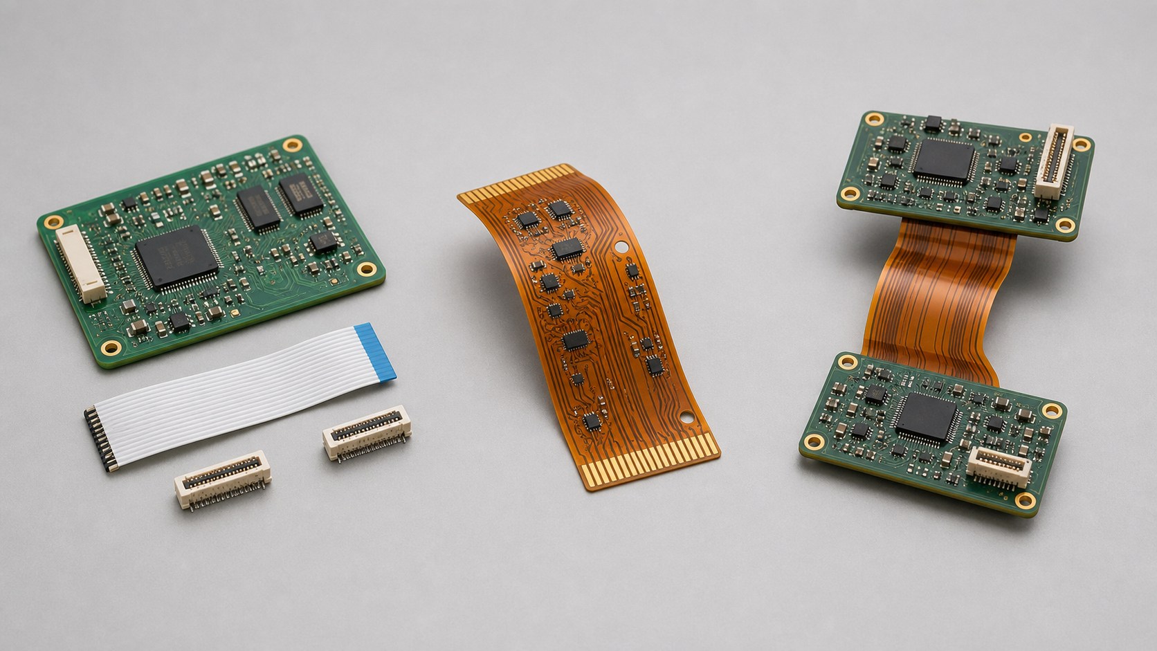
A rigid PCB uses a dimensionally stable laminate, commonly an FR-4-type material, and is not intended to bend in normal use. When two rigid boards must sit at different angles or move relative to one another, the product needs a separate interconnect such as a board-to-board connector, ribbon cable, or wire harness.
Flex PCB: A Bendable Circuit
A flex PCB uses a thin flexible dielectric, commonly polyimide, so the circuit itself can bend or fold. The term flex covers several operating conditions. A section folded once during assembly and held in place has different material and routing requirements from an active bend area that moves repeatedly during service. Copper construction, thickness, layer count, bend radius, and trace orientation all affect whether a flex circuit is suitable for the intended motion.
Rigid-Flex PCB: Rigid and Flexible Zones in One Board
A rigid-flex PCB combines rigid component-mounting zones and flexible interconnect zones in one laminated board. The flex sections may be used for a one-time installation fold, occasional movement, or repeated dynamic motion. The label “rigid-flex” alone does not define the bend duty.
Connectors and Space Requirements
Separate Rigid PCBs Need Connectors or Harnesses
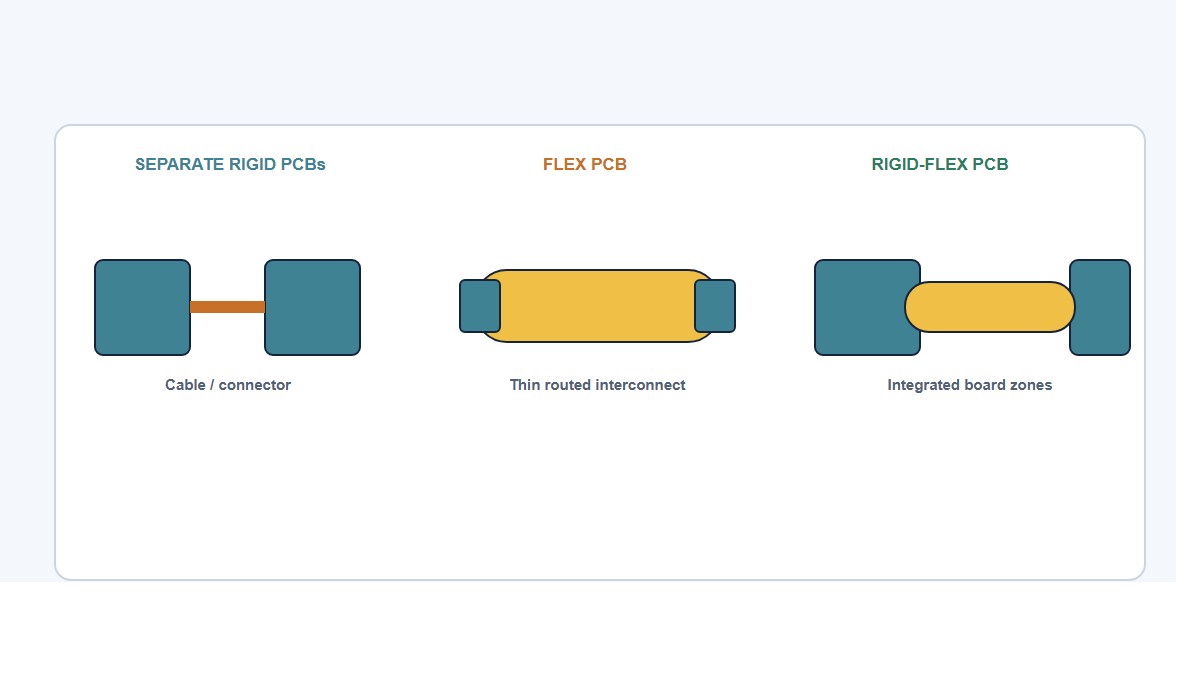
Separate rigid boards need a discrete path for signals and power between them. Every connector and cable occupies space, adds a sourcing and assembly item, and introduces a mating interface that must remain accessible during manufacturing or service.
Flex PCBs Can Replace a Cable or Thin Interconnect
A flex circuit can serve as a thin, routed interconnect and may replace a cable assembly between boards or modules. It is not limited to a simple two-point tail: flex circuits can include branches, local stiffeners, component areas, and more complex shapes when the design does not require all rigid and flexible portions to be laminated into one permanent structure.
Rigid-Flex PCBs Integrate Multiple Board Zones
In a rigid-flex design, the rigid zones connected by the integrated flex sections do not need discrete connectors between those zones. This can reduce part count and interconnect volume, especially where connector height, cable loops, and strain-relief space are difficult to accommodate. The product may still use external, battery, test, or module connectors elsewhere in the assembly.
Space Savings Depend on the Enclosure
Space savings matter most in constrained three-dimensional assemblies such as wearables, cameras, compact sensors, and handheld instruments. A product with a roomy enclosure may gain little from replacing a connection that already fits comfortably.
Assembly, Repair, and Reliability Differences
Assembly and Repair of Separate Rigid PCBs
Separate rigid boards usually follow conventional SMT assembly, followed by cable routing and connector mating. Those interconnect operations remain separate manufacturing steps; some may be automated or fixture-assisted at higher volume, depending on connector type, cable behavior, and product geometry.
This architecture is also comparatively modular. A damaged cable or connector can sometimes be replaced without discarding the boards, which can be valuable when field service, upgrades, or late design changes are expected.
Handling Flex and Rigid-Flex Assemblies
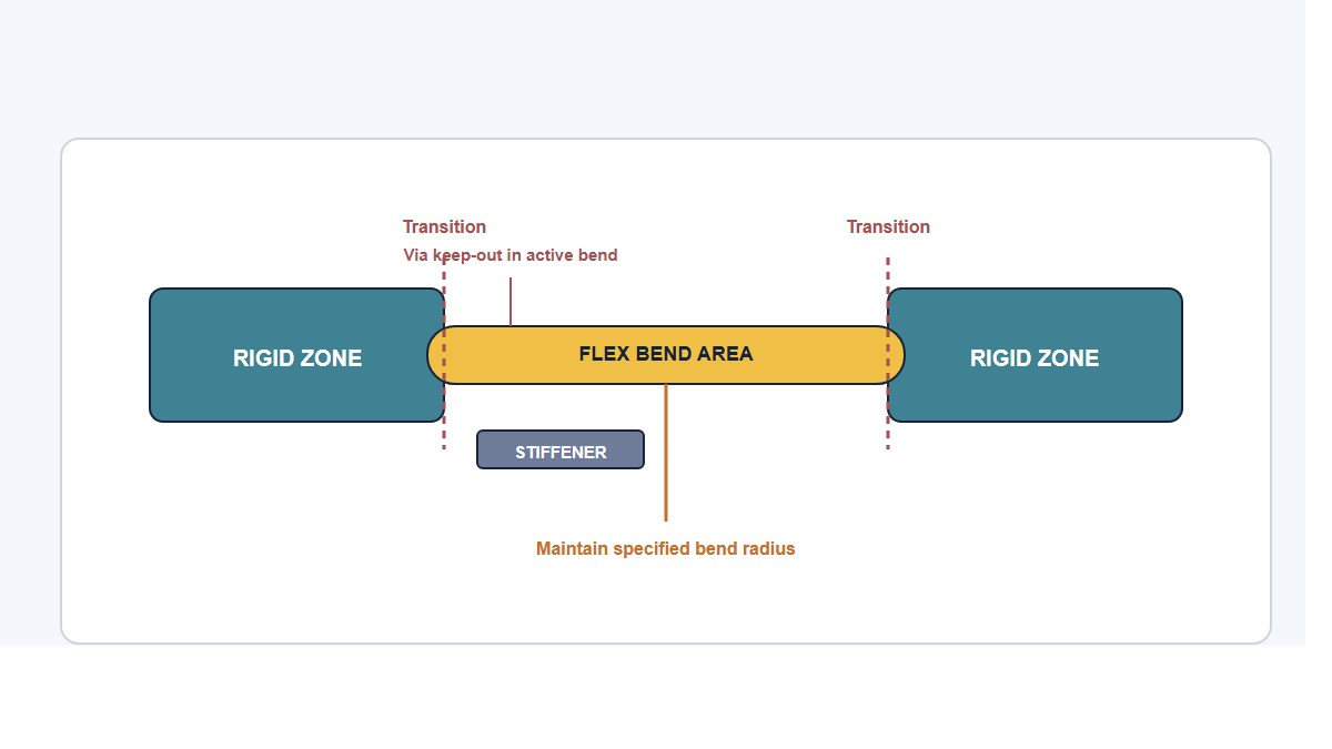
Flex and rigid-flex assemblies require controlled handling. The assembly process must keep each flexible section within its permitted bend direction and radius. Components or connectors placed on flexible material may need local stiffeners, while active bend regions should remain free of features that concentrate strain.
Rigid-flex fabrication also requires more demanding lay-up, registration, lamination, and protection of the flex areas. Some constructions require sequential lamination. Flex-zone opening may use controlled-depth routing, milling, laser processing, or another controlled method supported by the fabricator. Final assembly may include folding the board into its installed three-dimensional shape.
Rigid-flex does not remove reliability risk; it changes its location. Eliminating an intermediate connector can avoid contact wear, fretting, and cable strain-relief problems. The design must instead control copper fatigue in active bends, stress at rigid-to-flex or stiffener transitions, edge damage, and vias or solder joints placed too close to moving regions.
Reliability Risks in Bend and Transition Areas
Vias, plated holes, and solder joints should generally be kept out of active bend areas and away from rigid-to-flex transitions. They are not automatically prohibited from every non-bending flex area, provided the construction, local reinforcement, and manufacturing process support them.
A well-designed rigid-flex assembly can avoid connector-related contact risks in a vibration-heavy product, but only when its actual mechanical load, bend duty, transition geometry, and material construction have been defined correctly. The board type alone does not determine the result.
Bare-Board Cost vs. Total System Cost
Why Rigid PCBs Usually Cost Less to Fabricate
For otherwise comparable requirements, a conventional rigid PCB will generally have the lowest bare-board fabrication cost. Flex circuits add specialized materials and processing, while rigid-flex adds more complex lay-up, registration, lamination, flex-area protection, and inspection.
Greater process complexity also creates more opportunities for registration, lamination, and handling defects. Its effect on yield and price depends on the specific stackup and the fabricator’s process maturity; it should not be treated as a fixed penalty for every rigid-flex design.
What the Bare-Board Price Does Not Include
Bare-board price is only one part of the decision. A system using separate rigid boards may also include connectors, cable assemblies, strain relief, fastening hardware, assembly labor, and inspection or rework associated with those parts. Rigid-flex can remove some of those items where the integrated flex sections replace separate interconnects, but it shifts cost into a more specialized board, tooling, design verification, and potentially higher scrap exposure if one integrated section is defective.
How Design Maturity and Production Volume Affect Cost
Design maturity matters as much as volume. During early development, a modular rigid-board-and-cable architecture is often easier to change because board partitioning and interconnect length can be revised independently. Once the mechanical layout and electrical partition are stable, rigid-flex may become more attractive if the eliminated parts and assembly operations are significant enough to offset its fabrication, tooling, testing, and redesign costs.
Higher volume does not automatically make rigid-flex cheaper. The system economics improve only when the integrated structure removes enough material, labor, space, or reliability exposure to justify the more demanding bare-board process.
When to Choose Rigid, Flex, or Rigid-Flex PCB
The selection should follow the physical and manufacturing constraints of the product rather than an assumption that one structure is inherently more modern or capable.
| Design conditions | Structure that may fit | Main trade-off |
|---|---|---|
| Room for connectors, changing board partition, modular replacement, or field serviceability | Separate rigid PCBs with connectors or a harness | More interconnect parts and separate assembly operations |
| A thin or bendable interconnect is needed without integrating all rigid areas into one laminated board | Flex PCB | Requires controlled termination, handling, and bend design |
| Several rigid mounting zones must fit within a constrained three-dimensional assembly, and integrated static or dynamic flex sections provide system-level value | Rigid-flex PCB | More specialized fabrication and greater redesign exposure |
Choose Separate Rigid PCBs When Modularity Matters
Separate rigid boards tend to fit products that value modularity, repairability, straightforward prototyping, and low-risk design changes. They are also practical when the enclosure has enough room for connectors and cable routing.
Choose a Flex PCB When the Main Requirement Is a Bendable Interconnect
A flex circuit tends to fit when the central requirement is a thin, shaped, or moving interconnect and the design does not need all rigid and flexible portions to be laminated into one structure. It may connect boards, support local components, or route through a constrained mechanical path.
Choose a Rigid-Flex PCB When Several Rigid Zones Must Work as One Assembly
Rigid-flex tends to fit when multiple rigid mounting zones must be connected within a controlled three-dimensional form and removing intermediate connectors or cables provides enough space, assembly, or reliability value to justify the more specialized board.