
PCB Assembly Inspection and Testing Services
SugaMed provides in-process inspection, electrical testing, and functional testing support for medical electronics PCBA, including 3D SPI, AOI, X-ray inspection, ICT, functional testing, automated testing, firmware programming, and burn-in testing.
Inspection and testing requirements vary from one PCBA to another. The appropriate inspection and test plan depends on the PCB design, component packages, production stage, test-point availability, and customer-approved test requirements.
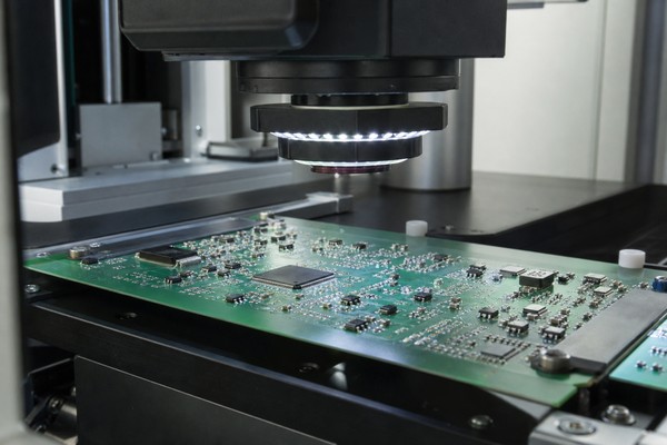
PCB Assembly Inspection and Testing Capabilities
PCB Assembly quality control covers the entire production process, from solder paste printing and component placement to soldering and final testing.
Not every PCBA requires all of these inspection and testing methods.
For example, a standard SMT PCBA may primarily require SPI and AOI. A board containing BGA components may also require X-ray inspection. If the project requires additional verification of electrical connectivity or specified functions, ICT, functional testing, or suitable automated testing may be added based on the PCB design, test interfaces, and customer requirements.
| Inspection / Test | Primary Purpose | How SugaMed Applies It |
|---|---|---|
| 3D SPI | Inspect solder paste deposition | In-process inspection before SMT placement, with 3D solder paste inspection from 0 to 450 μm |
| AOI | Detect visible placement and soldering defects | 100% post-reflow AOI for prototype SMT assemblies |
| X-ray Inspection | Inspect hidden solder joints | 100% X-ray inspection of BGA solder joints; QFN/LGA inspection based on project requirements |
| First Article Inspection | Confirm the assembly condition of the first unit for a new project or revision | Performed according to NPI and project requirements |
| ICT | Check circuit connectivity and selected component electrical characteristics | Applied based on test-point availability, fixture design, and project suitability |
| Functional Testing | Verify specified PCBA functions | Performed according to customer-approved test procedures and acceptance criteria |
| Automated Testing | Automatically perform specified electrical or functional tests | Suitable for projects with defined test methods and interfaces |
| Programming | Program firmware into the PCBA | Performed according to the firmware version and project documentation |
| Burn-In | Evaluate operation under specified conditions over a defined period | Scheduled according to product and customer test requirements |
3D SPI
Primary Purpose
Inspect solder paste deposition
How SugaMed Applies It
In-process inspection before SMT placement, with 3D solder paste inspection from 0 to 450 μm
AOI
Primary Purpose
Detect visible placement and soldering defects
How SugaMed Applies It
100% post-reflow AOI for prototype SMT assemblies
X-ray Inspection
Primary Purpose
Inspect hidden solder joints
How SugaMed Applies It
100% X-ray inspection of BGA solder joints; QFN/LGA inspection based on project requirements
First Article Inspection
Primary Purpose
Confirm the assembly condition of the first unit for a new project or revision
How SugaMed Applies It
Performed according to NPI and project requirements
ICT
Primary Purpose
Check circuit connectivity and selected component electrical characteristics
How SugaMed Applies It
Applied based on test-point availability, fixture design, and project suitability
Functional Testing
Primary Purpose
Verify specified PCBA functions
How SugaMed Applies It
Performed according to customer-approved test procedures and acceptance criteria
Automated Testing
Primary Purpose
Automatically perform specified electrical or functional tests
How SugaMed Applies It
Suitable for projects with defined test methods and interfaces
Programming
Primary Purpose
Program firmware into the PCBA
How SugaMed Applies It
Performed according to the firmware version and project documentation
Burn-In
Primary Purpose
Evaluate operation under specified conditions over a defined period
How SugaMed Applies It
Scheduled according to product and customer test requirements
What Is the Difference Between PCB Inspection, Electrical Testing, and Functional Testing?
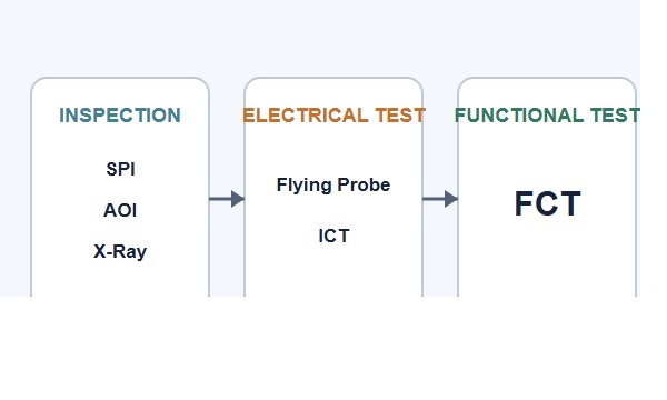
SPI, AOI, X-ray inspection, ICT, and functional testing are often collectively referred to as “PCB testing,” but each method verifies different aspects of the assembly.
AOI and X-ray inspection can help identify assembly or solder joint defects, but they cannot prove that the entire PCBA functions correctly. Functional testing can verify customer-specified functions, but it cannot replace soldering and assembly quality inspections.
Most projects require a combination of methods based on risk and verification objectives rather than relying on a single inspection or testing method.
For more information about how different testing methods work and when they are appropriate, see PCB Assembly Testing Methods and Their Applications.
Process Inspection
SPI
Solder paste deposition
Assembly Inspection
AOI, X-ray inspection, first article inspection
Component placement and solder joint condition
Electrical Testing
ICT and project-specific electrical checks
Circuit connectivity and selected component electrical characteristics
Functional Testing
Functional testing and applicable automated functional tests
Customer-defined PCBA functions and responses
Extended Testing
Burn-in
Operation under specified conditions for a defined period
| Category | Common Methods | Primary Verification |
|---|---|---|
| Process Inspection | SPI | Solder paste deposition |
| Assembly Inspection | AOI, X-ray inspection, first article inspection | Component placement and solder joint condition |
| Electrical Testing | ICT and project-specific electrical checks | Circuit connectivity and selected component electrical characteristics |
| Functional Testing | Functional testing and applicable automated functional tests | Customer-defined PCBA functions and responses |
| Extended Testing | Burn-in | Operation under specified conditions for a defined period |
Process Inspection
Common Methods
SPI
Primary Verification
Solder paste deposition
Assembly Inspection
Common Methods
AOI, X-ray inspection, first article inspection
Primary Verification
Component placement and solder joint condition
Electrical Testing
Common Methods
ICT and project-specific electrical checks
Primary Verification
Circuit connectivity and selected component electrical characteristics
Functional Testing
Common Methods
Functional testing and applicable automated functional tests
Primary Verification
Customer-defined PCBA functions and responses
Extended Testing
Common Methods
Burn-in
Primary Verification
Operation under specified conditions for a defined period
SugaMed’s PCB Assembly Inspection Coverage
Inspection requirements vary depending on component package types and the production stage. SugaMed determines the appropriate inspection coverage for each project.

Prototype SMT Assembly: 100% Post-Reflow AOI
For prototype SMT assemblies, SugaMed performs 100% post-reflow AOI.
Typical inspection items include:
- Missing or incorrect components
- Component misalignment
- Polarity and orientation errors
- Solder bridging
- Visible solder joint defects
- Other assembly issues detectable through optical inspection
AOI cannot inspect hidden solder joints or detect every electrical and functional issue. Additional inspection or testing may therefore be required based on component packages and project requirements.
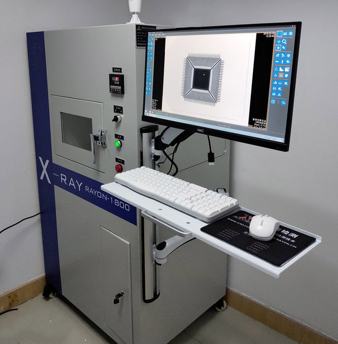
BGA Solder Joints: 100% X-ray Inspection
BGA solder joints are located beneath the package and cannot be fully inspected using standard visual inspection or AOI.
SugaMed performs 100% X-ray inspection of BGA solder joints to help identify:
- Solder ball alignment and consistency
- Bridging
- Voids
- Missing or visibly abnormal solder joints
- Other hidden soldering defects detectable through X-ray imaging
X-ray inspection is used to identify soldering and structural abnormalities visible in the images. It cannot, by itself, prove the complete electrical performance of every solder joint or the functional performance of the entire PCBA.
For QFN and LGA packages, whether X-ray inspection is required and what coverage is appropriate depends on the package structure, PCB design, process risk, and project requirements.
ICT and Functional Testing: Configured According to Project Requirements
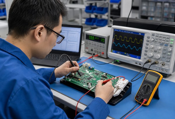
Whether ICT, functional testing, or applicable automated testing is required depends on several factors, including:
- PCB test points and test interfaces
- Circuit architecture
- Test fixture requirements
- Functions the customer needs to verify
- Test procedure
- Firmware requirements
- Production volume
- Pass/fail criteria
Simply specifying that “FCT is required” is usually not enough to accurately evaluate the test solution or prepare a quotation. Test content, test conditions, and acceptance criteria should be defined as early as possible during project introduction.
How to Define a PCBA Test Plan
More testing is not always better. An effective test plan should address the issues that genuinely need to be verified while also considering testability, production volume, and operating efficiency.
Key factors include:
For medical electronics projects, it is recommended to confirm the test scope, fixtures, firmware version, and acceptance criteria as early as possible during the NPI stage. This helps avoid defining the test method only after PCBA assembly has been completed.
| Factor | Impact on the Inspection and Test Plan |
|---|---|
| Component packages | Hidden solder joints, such as BGA connections, may require X-ray inspection |
| PCB test points and interfaces | Affect the feasibility and coverage of ICT, functional testing, and fixture design |
| Circuit design | Affects test methods, input/output conditions, and fixture design |
| Production stage | Prototype and volume production may require different testing priorities |
| Production volume | Influences the investment approach for dedicated fixtures and automated testing |
| Firmware | Affects programming and certain functional test procedures |
| Customer functional requirements | Define functional test items and pass/fail criteria |
| Traceability requirements | Determine which test and production records must be retained |
Component packages
Impact on the Inspection and Test Plan
Hidden solder joints, such as BGA connections, may require X-ray inspection
PCB test points and interfaces
Impact on the Inspection and Test Plan
Affect the feasibility and coverage of ICT, functional testing, and fixture design
Circuit design
Impact on the Inspection and Test Plan
Affects test methods, input/output conditions, and fixture design
Production stage
Impact on the Inspection and Test Plan
Prototype and volume production may require different testing priorities
Production volume
Impact on the Inspection and Test Plan
Influences the investment approach for dedicated fixtures and automated testing
Firmware
Impact on the Inspection and Test Plan
Affects programming and certain functional test procedures
Customer functional requirements
Impact on the Inspection and Test Plan
Define functional test items and pass/fail criteria
Traceability requirements
Impact on the Inspection and Test Plan
Determine which test and production records must be retained
Functional Testing for Medical Electronics PCBA
Functional testing for medical electronics PCBA is primarily used to verify that customer-specified circuit functions, interface responses, and outputs meet the defined test requirements. It is not equivalent to complete medical device performance validation or regulatory certification.
Depending on the project, functional testing may include:
- Power-on checks
- Voltage and current measurements
- Input/output response
- Communication interfaces
- Sensor interface response
- Display or control signals
- Alarm and control outputs
- Other customer-specified PCBA functions
The specific test content, input conditions, and acceptance criteria must be defined based on the circuit design and the customer-approved test procedure.
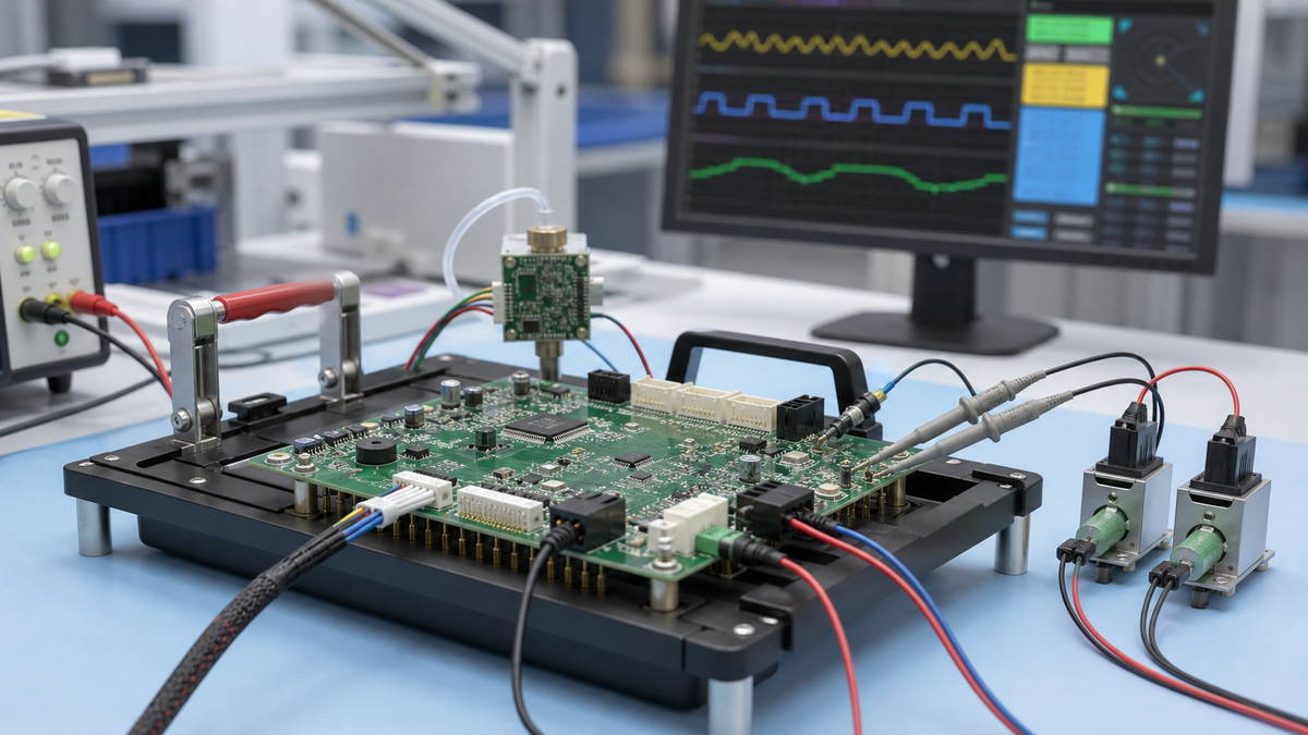
Functional Testing for Blood Pressure Monitoring PCBA
For applicable blood pressure monitoring electronics projects, a BPM test fixture may be used to verify specified PCBA functions according to the approved test plan.
The test scope is defined by the project requirements. Board-level functional testing should not be considered equivalent to verifying the blood pressure measurement accuracy or final product performance of the complete device.
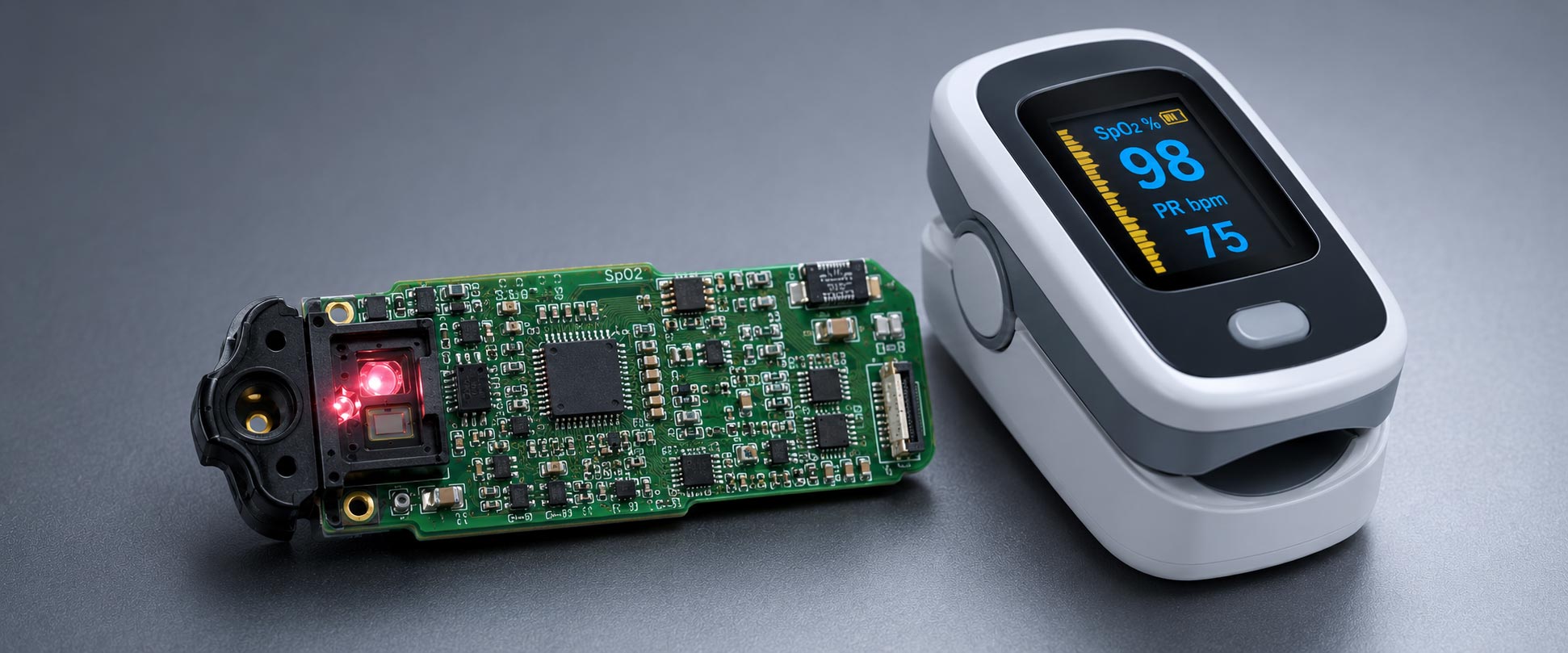
Functional Testing for SpO₂-Related PCBA
For applicable projects, SpO₂ simulation testing may be used to verify relevant PCBA interfaces and specified functions.
Input conditions, test methods, and pass/fail criteria must be defined during project introduction.
Other Medical Electronics PCBA
For patient monitoring, diagnostic, and therapeutic medical electronics projects, SugaMed can configure functional testing, ICT, automated testing, programming, or burn-in according to customer-provided or mutually approved test procedures.
Because circuit designs and testing requirements vary significantly between products, the specific test plan must be defined on a project-by-project basis.
How Firmware Programming Works with Functional Testing
For PCBA with MCUs, memory devices, or other programmable components, firmware programming can be scheduled before functional testing or at another appropriate stage in the production process, depending on project requirements.
Customers typically need to provide:
- Firmware files
- Firmware version
- Programming instructions
- Target device information
- Version control requirements
If functional testing depends on a specific firmware version, the corresponding PCB Revision, BOM Revision, Firmware Version, and Test Procedure Revision should be clearly identified. This helps ensure that the production configuration and test conditions remain consistent.
When the PCB, BOM, firmware, or test procedure changes, these revision identifiers also make it easier to confirm the applicable production configuration, programming version, and test status.
Medical PCBA Test Records and Traceability
For medical electronics projects, test results are only one part of the overall quality record. According to project requirements, SugaMed can link inspection and test status to relevant production information.
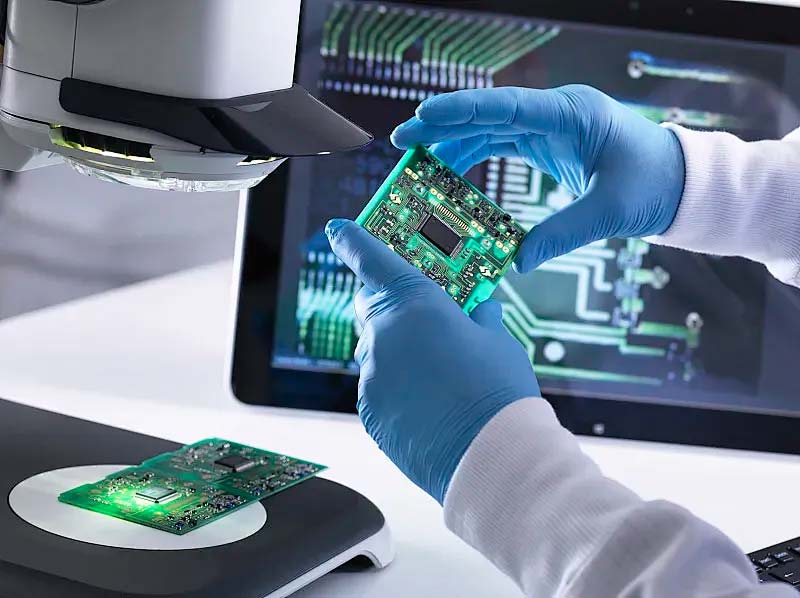
Lot and Component Traceability
Depending on project requirements, records may include:
- Production lot
- PCB manufacturing lot
- Critical component lots
- Related manufacturing and inspection records
Serial Number Traceability
For projects requiring individual board identification, PCBA-level serial number traceability can be established. Relevant production configuration and test status can also be linked according to customer requirements.
Test Records
Depending on project requirements, test records may include:
- Test result/status
- Test date
- Production lot
- Serial number
- Firmware version
- Test procedure revision
- Related production and inspection information
Production and quality records for medical projects may be retained for at least 10 years in accordance with project requirements and the applicable quality management system.
Related manufacturing, inspection, and testing records can also be organized and provided according to customer-agreed documentation and traceability requirements, supporting the customer’s own quality records and product traceability system.
Every Inspection Method Has Its Limitations
No single inspection or testing method can identify every potential issue. The appropriate combination of methods should be determined according to the project requirements.
AOI: Suitable for inspecting component placement and visible solder joints, but it cannot fully inspect hidden connections beneath packages such as BGAs.
X-ray inspection: Suitable for inspecting hidden solder joints and internal structural abnormalities, but it cannot determine whether an MCU, communication interface, or other circuit function operates correctly.
ICT: Suitable for checking certain circuit connections and component electrical characteristics, but its coverage is limited by test-point availability and circuit design.
Functional testing: Verifies customer-defined PCBA functions and pass/fail criteria, but it is not equivalent to complete medical device system validation, performance validation, or regulatory certification.
Frequently Asked Questions
Does every PCBA require ICT and functional testing?
No.
Whether ICT, functional testing, or automated testing is required depends on the PCB design, test points, production volume, product requirements, and customer-approved test plan.
Some PCBAs may only require in-process inspection and specific electrical checks, while others may require additional functional verification.
What is the difference between AOI and functional testing?
AOI primarily checks component placement and visible soldering defects, such as missing components, misalignment, polarity errors, and solder bridging.
Functional testing verifies customer-defined PCBA functions, such as input/output behavior, communication interfaces, or other specified electrical responses.
They verify different aspects of the assembly and cannot replace one another.
Does SugaMed perform X-ray inspection on all BGA connections?
Yes.
SugaMed performs 100% X-ray inspection of BGA solder joints.
For QFN and LGA packages, the appropriate inspection method is determined based on the package structure, PCB design, process risk, and project requirements.
Who provides the functional test procedure?
The customer typically provides the functional definition, test method, and pass/fail criteria. Alternatively, these requirements may be mutually defined during project introduction based on the customer’s product requirements.
SugaMed performs the applicable PCBA functional testing according to the approved test requirements.
Can SugaMed perform firmware programming and functional testing in the same production process?
Yes.
Depending on project requirements, firmware programming can be integrated into the production process together with functional testing, ICT, or applicable automated testing.
The sequence depends on the target device, firmware, and test method.
Does SugaMed support dedicated functional testing for medical electronics PCBA?
Yes, where required by the project.
For example, applicable projects may use a BPM test fixture or SpO₂ simulation testing. The specific test scope, conditions, and acceptance criteria must be confirmed during project initiation.
How long are medical PCBA production and test records retained?
Under SugaMed’s current quality management requirements for medical projects, relevant production and quality records may be retained for at least 10 years.
The specific test data, production records, and traceability information to be retained should be defined according to customer and project requirements.
Submit Your PCB Assembly Testing Requirements
If your medical electronics PCBA requires AOI, X-ray inspection, ICT, functional testing, automated testing, firmware programming, burn-in, or other project-specific testing, send your available manufacturing documentation and test requirements to SugaMed.
Recommended documentation includes:
Gerber Files + BOM + Assembly Drawing + PCBA Quantity + Firmware + Test Procedure + Pass/Fail Requirements
Our engineering team will evaluate the appropriate inspection and testing plan based on the PCB design, component packages, test conditions, and production requirements.