TENS / EMS Therapy Device PCB Assembly
Home » Therapeutic Device PCBA » TENS / EMS PCB Assembly
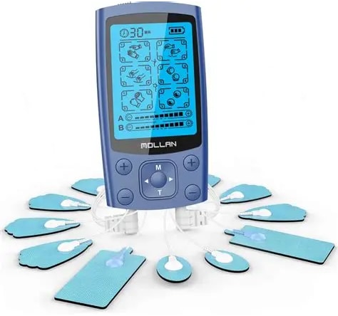
TENS / EMS PCBA manufacturing for wearable, wellness, and medical stimulation devices — from NPI and prototype builds to certified medical-grade assembly and volume production.
What is TENS / EMS PCB Assembly?
TENS / EMS PCB assembly refers to the manufacturing of printed circuit boards used inside nerve and muscle stimulation therapy devices — including the biphasic pulse generation boards that produce stimulation waveforms, the constant-current output stages that deliver controlled pulses to skin electrodes, the isolation-related layout that supports patient-side electrical safety, and the supporting boards for power, user controls, and wireless connectivity.
These boards sit at the electronics core of the device. Pulse stability, output behavior across changing electrode-skin impedance, and patient-side electrical safety all depend on PCBA design and assembly decisions made before the first prototype is built.
Sugamed manufactures PCBA for both prescription medical TENS / EMS programs and consumer health stimulation products — under ISO 13485 and IPC-A-610 Class 3.
TENS / EMS Devices We Build PCBA For
Who builds your boards
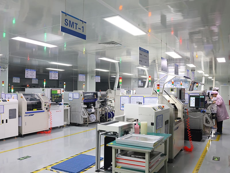
Sugamed operates a manufacturing facility with 15 Fuji and Yamaha SMT lines, 10 automatic through-hole insertion machines, multiple dedicated bonding stations, 18 PCBA assembly lines, and 40+ box-build assembly lines. Total headcount exceeds 1,100 employees.
Within this capacity, dedicated medical lines are kept separate from industrial and consumer programs — relevant for high-voltage component handling, isolation-related layout discipline, and the traceability discipline ISO 13485 requires.
We assemble PCBA across respiratory therapy, infusion, neurostimulation, patient monitoring, and emergency cardiac programs. Engineers on our medical team have worked on TENS pulse generator, EMS multi-channel output, and wearable stimulator board projects across multiple programs — including both prescription and consumer health regulatory paths.
Where TENS / EMS PCBA Gets Hard
Pulse instability, electrode lead-off failures, output behavior drift, EMC issues — all catchable earlier.
01 · Constant current isn't constant if your output stage drifts
Skin-electrode impedance varies from 500Ω dry contact to 5kΩ as gel dries out — and your patient feels every ohm of variation as inconsistent stimulation. Output stage design has to compensate for this in real time, not at calibration. Output stage topology, current sense feedback, and voltage headroom reviewed at DFM — before the design assumes ideal electrodes.
02 · High-voltage rails on a small board need real layout discipline
High-voltage output rails sharing a board with a microcontroller, BLE module, and battery management circuitry require explicit creepage and clearance planning — not assumptions. Output transformer placement, isolation barriers, and high-voltage routing affect both safety and EMC behavior. Creepage, clearance, and isolation-related layout reviewed at DFM — and again at first article inspection.
03 · Lead-off and electrode fault detection determines field reliability
A loose electrode shouldn't just stop stimulation — it has to detect, alert, and reset cleanly. Detection circuitry that triggers false faults annoys users into disabling safety features. Detection that misses real faults creates safety incidents. Lead-off detection thresholds, debounce timing, and recovery logic reviewed against your alert and safety strategy at DFM.
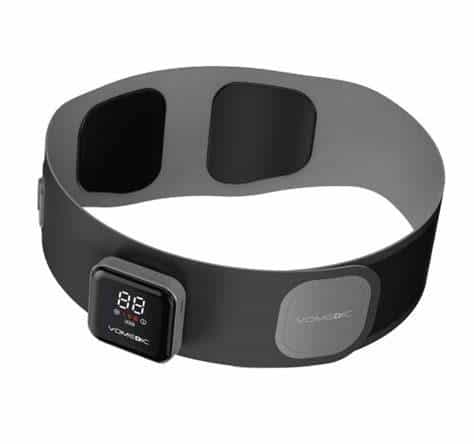
04 · Wearable EMS multiplies every problem above into compact form factors
Wearable stimulators ask the board to deliver high-voltage output, BLE connectivity, battery management, and isolation-related layout on a flexible or rigid-flex substrate often under 30 cm². Component density, thermal behavior under continuous use, and connector reliability through wash cycles become the dominant failure modes. DFM review covers thermal margins, flex-zone routing, connector strain relief, and RF layout considerations for connected stimulation devices.
Compliance & Quality Standards
Medical PCBA quality is built across three layers — the standards we manufacture under, the process checkpoints embedded in every build, and the test controls applied to TENS / EMS-specific failure modes. Each layer is set at design review, not added after first article.
Layer 1 — Standards we manufacture under
We assemble medical PCBA under the following standards as a manufacturer:
- ISO 13485 — medical device quality management system
- IPC-A-610 Class 3 — workmanship for high-reliability electronics
- IEC 60601-1 — experience supporting customers developing IEC 60601-1 compliant medical devices, with general safety considerations integrated at DFM
- IEC 60601-1-2 — EMC behavior reviewed at design stage to support customer EMC compliance work
- IPC-J-STD-001 — soldering process compliance for medical-grade assembly
Device-level certification — including emerging respiratory standards such as ISO 80601-2-94 (currently in development) — sits with the customer. Our manufacturing records are formatted to feed into your DHF and regulatory submission workflows.
Layer 2 — Process checkpoints
① Design Review (DFM / DFT) Constant–current output topology, high-voltage rail routing, isolation barrier placement, lead-off detection logic, BLE coexistence, and BMS topology — reviewed before BOM commits.
② Assembly Floor Dedicated medical lines. Inline AOI on every board. X-Ray for BGA, QFN, and high-density packages. ESD-controlled environment throughout.
③ Documentation Lot-level component traceability. AOI and X-Ray image archives. Functional test records. Process validation documentation. Output formatted for FDA 510(k), EU MDR, and NMPA workflows.
Layer 3 — TENS / EMS-specific test controls
Standard medical PCBA controls plus the following, set during design review:
- Functional verification aligned with customer-defined stimulation profiles
- Constant-current behavior validated across typical electrode impedance ranges
- Lead-off detection response and threshold verification
- Isolation-related layout, creepage, and clearance reviewed during DFM and validated as part of customer safety verification workflows
- High-voltage transformer and isolation component inspection at incoming
- Burn-in testing for continuous-duty stimulator boards
FAQ
What's the difference between TENS, EMS, and IFC PCBA?
All three deliver controlled current pulses to skin electrodes, but the output requirements differ. TENS targets sensory nerve fibers with low-current high-frequency pulses for pain modulation. EMS / NMES drives motor nerves with higher current at lower frequency to trigger muscle contraction. IFC uses two intersecting medium-frequency channels to produce a low-frequency beat at depth. The board engineering — pulse generation topology, output stage, channel architecture — varies meaningfully between them.
Can you assemble high-voltage output stages safely?
Yes. Biphasic high-voltage output rails, transformer-coupled or boost-converter topologies, with creepage and clearance reviewed at DFM. Isolation-related layout verified at incoming inspection and again at functional test. ESD and high-voltage handling procedures apply throughout assembly.
Do you support both prescription medical and consumer/OTC TENS programs?
Yes. Medical lines and quality systems support both regulatory pathways. The board engineering is similar; the documentation and testing rigor differs by program. We adjust our manufacturing record output to match — full DHF feeds for prescription programs, OTC-appropriate documentation for consumer devices.
What's the lead time for a TENS / EMS PCBA prototype?
Typically 3–4 weeks from approved Gerber and BOM. Long-lead items — specialized transformers, isolation barriers, BLE modules — flagged at BOM review. Lead time confirmed then; current supply conditions can extend this for specialist components.
Do you support wearable EMS designs with rigid-flex or flex PCB?
Yes. Flex and rigid-flex assembly is part of our medical capability. Wearable stimulator builds get DFM review at three layers — electrical performance, mechanical reliability through wear cycles, and assembly feasibility on flexible substrates.
Do you support prototype-to-mass-production transitions?
Yes — that’s our core profile. The same engineering team and the same medical line carries your program from first-article through pilot and into volume production. Process validation, test fixture qualification, and traceability records build up across these stages so you don’t restart documentation when volumes scale.
Start your TENS / EMS PCBA project
Quote from our medical PCBA engineers within 24 hours.