ECG Patch PCB Assembly
Home » Patient Monitoring Device » ECG Patch PCB Assembly
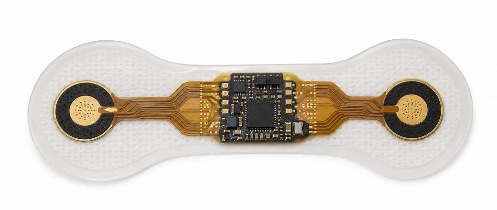
Flexible and rigid-flex PCBA for wearable cardiac monitoring patches
- ISO 10993 biocompatibility support
- 21 CFR 870.2800 / IEC 60601-2-47 documentation
ECG patches sit awkwardly between two industries. They’re medical devices in the regulatory sense — Class II, 21 CFR 870.2800, IEC 60601-2-47, the full file. But on the bench they behave like wearable consumer electronics: thin, low-power, battery-bound, glued to skin for a week or two at a time.
That mismatch is where most contract manufacturers struggle. A factory used to building bedside monitors will hand you a patch that meets every electrical spec and falls off the patient on day three. A factory used to consumer wearables will get the form factor right and miss the biopotential noise floor by 20 dB.
We’ve spent enough years on both sides to know where those failure modes show up — and most of them show up in manufacturing, not in design.
Our ECG Patch PCBA Capabilities
Flexible and Rigid-Flex Assembly
Most ECG patch designs we see now are rigid-flex — a small rigid island for the AFE and MCU, with flex tails running out to the electrode contacts. We assemble these routinely, on polyimide substrates from the usual suppliers (DuPont Kapton, Panasonic Felios). A few things that come up on every ECG patch program:
- Bend radius discipline. The flex sections in a patch see real mechanical stress every time the patient moves. We hold to 6× material thickness as the working minimum on dynamic flex sections, tighter on static. Layouts that ignore this rule fail at week two of wear, not at week one — which makes them expensive to find.
- Coverlay vs. soldermask transitions. The boundary between the rigid and flex sections is where most assembly defects show up. We've settled on a stiffener placement and adhesive flow approach that handles this without the cracking we used to see in early-generation patch designs.
- Component placement on flex. 0402 and 0201 work fine on flex with the right pad anchoring. BGA and large QFN don't — we'll flag that during DFM and propose alternatives.
Low-Noise Analog Front-End Manufacturing
We've assembled patch boards built around most of the chipsets you'd expect — TI ADS1292, ADS1291, AD8232, AD8233, and Maxim MAX30003 for the more recent single-lead AFE-on-chip designs. A handful of programs use MAX86150 for combined ECG and PPG. The chip selection isn't the hard part. The hard part is everything around it: layout, soldering profile, ESD handling on incoming AFE inventory, and protecting the analog input pins from the kind of static you pick up just walking across an SMT floor.
Signal Integrity for Biopotential Acquisition
ECG patches operate at signal levels where layout decisions show up directly in the recording. We support designs that need rigorous signal-integrity engineering — Driven Right Leg (DRL) circuit routing, EMI shielding, differential pair routing for biopotential signals, and analog/digital ground partitioning that actually holds up under battery-powered switching noise. Our DFM review covers electrode-skin impedance matching points, CMRR verification, input-referred noise control, lead-off detection circuit integrity, and baseline wander filtering for long-term ambulatory recordings. Motion artifact mitigation gets discussed across both single-lead and dual-lead patch architectures — the kind of detail that doesn't show up on a capabilities sheet but determines whether a 14-day recording is clinically usable.
Ultra-Low-Power and Battery Optimization
A patch lives or dies by its battery curve. Most of the designs we build target 7 to 14 days on a single coin cell or thin-profile lithium-polymer pack — typically CR2032, CR2450, or a 30–50 mAh Li-poly depending on the form factor. What we watch for during build:
- Sleep-mode current draw on the assembled board, measured before shipment, not just trusted from datasheet specs
- Decoupling capacitor placement around the AFE — affects sleep current more than people expect
- Battery contact integrity for designs that use spring contacts rather than soldered packs
- Charging circuit verification on reusable patch designs (less common than disposable, but growing)
Wireless Connectivity Integration
BLE 5.x is the default radio on almost every patch we build now. NFC shows up on some short-range data-dump designs. A few telemetry-class patches run cellular IoT (LTE-M or NB-IoT) for real-time MCT applications. Antenna placement on a wearable patch is a problem in itself — the human body detunes most antenna designs by several dB, and the shielding effect varies with electrode hydration. We'll review antenna keep-out zones during DFM and call out anything that's likely to underperform once the patch is on a patient rather than on a bench.
Biocompatibility and Patient-Contact Engineering
ISO 10993 is non-negotiable on patch programs. Every material that touches skin — enclosure resin, conformal coating, adhesive system, electrode interface — has to be on a controlled-materials list with documented biocompatibility testing.
We maintain that list internally and update it when suppliers change formulations (which happens more often than you’d think, and almost never gets communicated downstream unless someone is watching).
For coatings specifically, Parylene C is our default for skin-contact patch applications — it passes ISO 10993-5 cytotoxicity and ISO 10993-10 irritation cleanly, and it doesn’t change electrical properties on the AFE inputs the way some acrylic coatings do.
For programs that need full ISO 10993 testing support, we coordinate with the customer’s testing lab on coupons and witness samples cut from production batches. Not every customer needs this. The ones who do, need it badly.
Patient Monitor Applications We Support
Long-Term Ambulatory Monitoring
Holter replacement patches for 7 to 14-day continuous wear. The primary clinical use case, and the one that drives most of the wearability and battery-life constraints in the design.
Mobile Cardiac Telemetry (MCT)
Real-time arrhythmia detection with cellular or paired-smartphone uplink. Wireless integration (LTE-M, NB-IoT) is part of the PCBA scope, not an afterthought.
Atrial Fibrillation Screening
Single-lead patches optimized for paroxysmal AFib detection. Signal quality requirements are high — intermittent AFib is easy to miss if the recording has motion artifact or baseline wander.
Post-Procedure Monitoring
Short-duration patches for post-ablation or post-discharge monitoring. Wear duration is shorter but data quality standards are the same as long-term ambulatory builds.
Clinical Trial Cardiac Safety Monitoring & Remote Patient Monitoring
Patches used as ECG endpoints in pharmaceutical trials require the data quality and validation standards that come with regulated clinical research — validated test specifications, batch traceability to individual subject records, and audit trail integrity. RPM programs add the additional requirement of central station connectivity and HL7 integration at the system level.
Quality & Compliance
- ISO 13485 quality management system, audited annually
- FDA Class I and Class II documentation support — including DHF and DMR contributions
- IPC-A-610 Class 3 workmanship across all medical assemblies
- 100% functional testing on every patient monitoring PCBA before it ships
- Lot-level component traceability — every part traced back to authorized distributor and original manufacturer
- Counterfeit avoidance — sourcing only from franchised distributors and OEM-direct channels, no exceptions
FAQ
What's the difference between an ECG patch PCBA build and a Holter monitor PCBA build?
Form factor and wearability discipline. A Holter is a small box with electrodes on cables — the PCBA is rigid, the form factor is constrained but not extreme, and the wear interface is clothing, not skin. A patch puts the PCBA on a flexible substrate, glued directly to skin for 7 to 14 days, with all the biocompatibility and adhesive interface engineering that implies. Different build, different supply chain, different DFM rules.
Which AFE chips do you have manufacturing experience with?
Most of the medical-grade single-lead and dual-lead AFEs you’d expect — TI ADS1291/1292, ADI AD8232/AD8233, Maxim MAX30003, MAX86150 for combined ECG and PPG. We’re happy to work with other AFEs as long as we can secure them through franchised channels.
Can you build to IPX7 for showering compatibility?
Yes, with overmolding or Parylene C coating. It adds cost and process steps, and it changes the assembly flow significantly compared to IPX4 designs. Worth discussing during DFM whether the use case actually requires it.
What's the typical MOQ for ECG patch PCBA?
Prototypes start from low quantities — we’ve built first-article runs as small as 25 units. Production MOQs depend on the BOM and the AFE availability. Disposable patch programs that hit clinical volume usually run from 5,000 units per month and up.
How do you handle ISO 10993 material control?
We maintain an internal controlled-materials list for enclosure resins, conformal coatings, adhesives, and any other surface that contacts skin. When a supplier changes formulation, we requalify before bringing the new material into a patch program. For full ISO 10993 testing support, we coordinate witness coupons from production batches with the customer’s testing lab.
Do you provide 510(k) manufacturing documentation?
Yes. Manufacturing-side packet — process records, component traceability, DMR contributions, CAPA records. We don’t write the regulatory submission, but the manufacturing portion will be audit-ready when your regulatory affairs team puts the package together.
What's the prototype turnaround for an ECG patch design?
7 to 10 working days for standard rigid-flex patch builds, assuming the BOM is in stock or available with normal lead times. Faster for simpler single-board patch designs.
How do you ensure long-term battery performance on disposable patches?
Sleep-mode current is measured on the assembled board before shipment — not just trusted from datasheet specs. We’ve found firmware regressions and decoupling-related leakage issues this way that would otherwise have shown up in customer field testing.
Related PCBA Services
Other patient monitoring device categories we build PCBA for:
Ready to Move Your ECG Patch from Prototype to Production?
Send us your Gerber files, BOM, and a quick description of the wear duration and form factor target. We’ll come back with an engineering-reviewed quote, a DFM read on the rigid-flex sections, and an honest assessment of any signal integrity or wearability concerns we see in the design. We’d rather flag a problem during quoting than after the first build.