Medical Device PCBA

Blood Pressure Monitor PCB Assembly

Medical-grade PCBA for upper-arm, wrist, ambulatory, and wearable blood pressure monitors. Built for ±3 mmHg accuracy and a ten-year service life.

What Makes BPM PCBA Different from Ordinary Medical Electronics

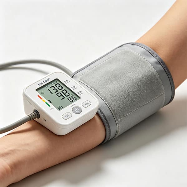
A blood pressure monitor PCB is one of the few medical boards where the same circuit has to do two things that pull in opposite directions. On one side of the board, a small electric pump and a solenoid valve are switching dozens of milliamps at a time, generating exactly the kind of broadband noise that any analog engineer learns to be afraid of. On the other side of the same board, a MEMS pressure sensor is producing microvolt-level signals that need to be amplified, filtered, and digitized accurately enough to determine systolic and diastolic pressure within ±3 mmHg.

Blood pressure monitor PCB layout diagram showing analog and digital ground partitioning between pressure sensor section and pump driver section

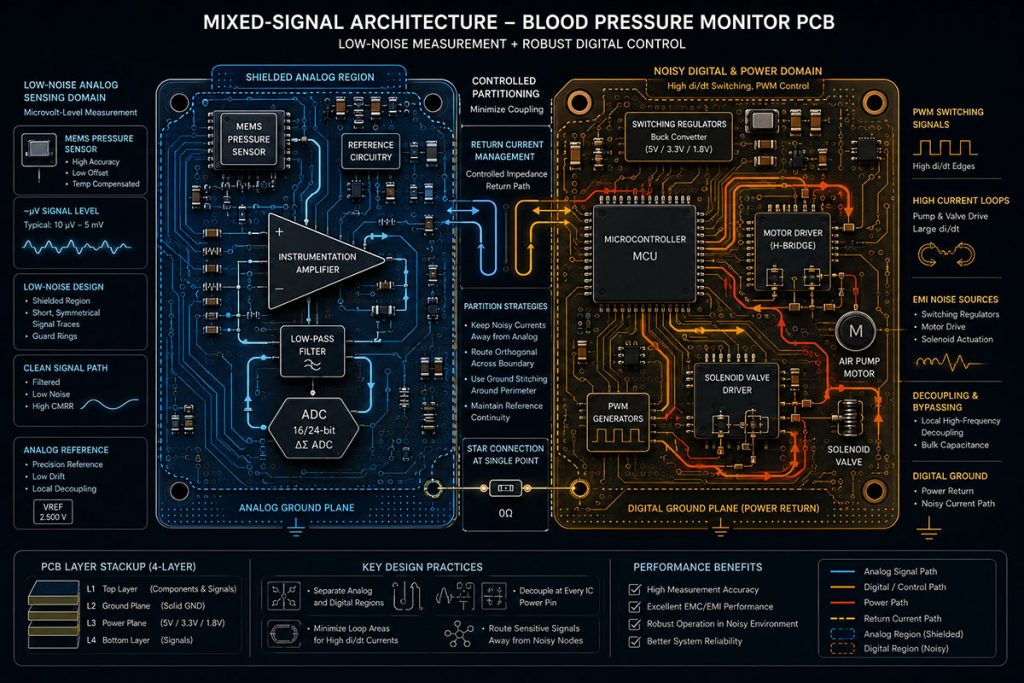
This is why a four-layer board with carefully partitioned analog and digital ground planes is more or less the minimum viable configuration for a serious BPM design — and why consumer-electronics assembly processes often run into problems in BPM production. The accuracy specification has to hold not for a week, not for a year, but across the full service life of the device. That single requirement reaches back through the whole manufacturing chain: laminate selection, solder profile, sensor placement, conformal coating, even the way you handle MSL-rated components on the line.

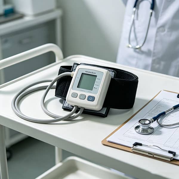
There is also a second layer that is an area where general-purpose EMS factories often run into trouble. A home blood pressure monitor — even a thirty-dollar one sold in a pharmacy — has to clear IEC 60601-1 for general medical electrical safety, IEC 60601-1-2 for EMC, and IEC 80601-2-30 for the BPM-specific safety standard. A consumer electronics line will not pass an audit against any of these, regardless of how good its yield numbers look.

BPM Form Factors We Build PCBA For

Blood pressure monitors come in five distinct form factors, and the manufacturing requirements for each one are surprisingly different. The table below summarizes how we approach them.

Upper-arm-home-blood-pressure-monitor-with-inflated-cuff
Clinical-ambulatory-blood-pressure-monitor-(ABPM)-device
Form Factor Typical Layer Count Surface Finish Key Manufacturing Focus Volume Profile
Upper-Arm Home BPM 4 HASL Lead-Free Pump-driver noise isolation, calibration stability Mid- to high-volume
Wrist BPM 4 (often HDI) ENIG Miniaturization, sweat-resistant coating, BLE integration Mid-volume
Ambulatory BPM (ABPM) 6 ENIG Low-noise pump driver, 24-hour power management, on-board logging Low-to-mid volume, high mix
Wearable / Cuffless BPM 4–6 (Rigid-Flex) ENIG / Immersion Silver Fine-pitch sensor placement, multi-channel analog routing Low volume during NPI, scaling fast
Clinical / Office BPM 4–6 HASL or ENIG Higher accuracy class (±2 mmHg), often multi-parameter integration Low-to-mid volume

The upper-arm category is still the bulk of the global market by unit volume, and most of our BPM work falls here. The wrist category looks similar on the surface but quietly imposes a different problem set — sweat ingress, smaller sensor real estate, and tighter BLE antenna constraints. ABPM is where the engineering gets interesting: a clinical-grade ambulatory monitor has to run for 24 hours on a battery, drive a pump quietly enough not to wake the patient at night, and log data reliably across that entire window. The cuffless wearable category is the newest and the fastest-growing, and it brings rigid-flex assembly and skin-contact considerations into the picture.

What We Focus On When Building a BPM Board

Our role is manufacturing, not algorithm design. The algorithm — whether it’s the standard oscillometric method or one of the newer cuffless approaches — belongs to our customers. What we focus on is everything that determines whether the algorithm will actually get a clean signal to work with once the device is in production.

In practice, our DFM reviews on BPM designs tend to concentrate on the same handful of issues, regardless of the customer’s specific architecture. Pressure sensor routing is usually the first thing we look at — the traces from the MEMS sensor to the instrumentation amplifier are the most noise-sensitive section of the board, and small layout decisions there end up driving most of the long-term accuracy outcomes. Analog and digital ground partitioning is the second focus area, because the pump driver and the analog front-end share a power source and need to be electrically isolated from each other in a way that survives the EMC test. ADC reference voltage stability is the third — a drifting reference will quietly corrupt every measurement the device ever takes, and it’s surprisingly common in designs that haven’t been carefully reviewed.

Beyond layout, the manufacturing-side decisions that matter most are laminate selection (high-Tg FR4 is essentially mandatory for long-term calibration stability), MEMS pressure sensor handling (these parts are MSL-rated and unforgiving about reflow profile), and conformal coating strategy for any form factor that will see moisture or sweat. None of these are exotic processes individually. The trick is doing all of them together, on the same board, without one process creating problems for another later in production.

Engineering Capabilities for BPM Production

A few capabilities we apply specifically to blood pressure monitor work:

Analog–digital ground partitioning review.​ When customers send us a design, the first review pass is almost always about whether the analog return paths and the pump-driver return paths share copper they shouldn’t. We send written feedback before tooling.

High-Tg laminate stocking.​ We keep medical-grade high-Tg FR4 from a small set of approved suppliers (Shengyi S1141, ITEQ IT-180A, and a couple of others depending on the customer’s qualification list). Material substitutions are a common cause of long-term calibration drift, so we don’t make them quietly.

Conformal coating and selective potting.​ Required for wrist devices, ambulatory devices, and any form factor that will see contact with skin or moisture. We do selective coating around connectors and test points — uniform coating across the whole board is a common shortcut that creates problems later.

MEMS sensor SMT process.​ Pressure sensors are MSL-3 or MSL-4 components in most cases. We track moisture exposure, dry-bake when necessary, and run a reflow profile that’s been verified against the specific sensor’s datasheet — not a generic profile.

These aren’t theoretical capabilities. They’re the things that go wrong on BPM programs when a non-specialist factory takes the project, and they’re the reason customers come to us after their first one didn’t go well.

aoi-test

Process and Quality Control

Every BPM PCBA we ship goes through the same four-stage quality process, with one stage that's specific to this product category. Incoming material inspection covers component authenticity (sourcing only from franchised distributors), MEMS sensor moisture-level verification, and laminate batch confirmation. Counterfeit pressure sensors are a real risk in the medical electronics supply chain, and we don't take chances on this. In-process control during SMT covers the standard SPI, AOI, and X-Ray steps, plus a process check specifically for the MEMS sensor reflow profile. Pressure sensor MSL handling errors are one of the most common — and most expensive — failure modes on BPM lines, so we treat this as a separate checkpoint rather than folding it into the general SMT process. The functional test stage is where BPM production diverges from generic PCBA. We don't just verify that the board powers up and the firmware boots. We run the assembled board through a simulated inflation-deflation cycle on a calibrated pressure fixture, verify the ADC sampling integrity, and check that the pump-driver section doesn't induce noise on the analog return path. A BPM that passes a generic functional test can still fail in the field — we've seen it happen — which is why this stage is custom-configured for the product type. Final verification covers traceability documentation, lot-level component records, and audit-ready documentation packs sized to whatever the customer's regulatory submission requires.

FAQ

What PCB layer count is recommended for a digital blood pressure monitor?

Four layers is the practical minimum for any serious BPM design. The reason is the analog–digital ground partitioning — two-layer boards force compromises in ground plane integrity that show up later as accuracy drift. Wearable and ambulatory designs often go to six layers when the form factor demands it.

We’ve worked with sensors from Honeywell (ABP and HSC families), TE Connectivity, Omron’s 2SMPB series, and several others depending on customer specification. The brand matters less than the MSL handling — pressure sensors are moisture-sensitive parts and require careful handling on the line.

Through layout review during DFM (we flag analog-digital ground sharing before tooling), through manufacturing process discipline on the H-bridge driver area, and through the functional test stage that simulates real inflation-deflation cycles to verify clean ADC sampling.

Yes. We provide the manufacturing-side documentation that goes into a customer’s regulatory submission against IEC 80601-2-30. We don’t write the submission itself, but we make sure the manufacturing record is audit-ready.

Yes, and the table earlier on this page lists the form factors we build for. The manufacturing approach differs significantly between the two — we don’t apply a single process across the board.

Prototypes ship in 7 to 10 working days. Production typically runs on a 4-to-6 week cycle once tooling is qualified, though this depends on BOM complexity and the lead times of the specific medical-grade components.

Start Your Blood Pressure Monitor PCBA Project

Upload your design files and BOM, and our engineering team will return a quote with DFM feedback within 24 hours. Whether you’re prototyping a new wearable BPM or transferring an existing upper-arm device from another supplier, we’ve handled the transition before.

Scroll to Top