
Digital Thermometer PCB Assembly
Home » Diagnostic Devices » Digital Thermometer PCB Assembly
PCBA manufacturing for digital thermometer programs — contact NTC, non-contact infrared, and wearable continuous-monitoring designs — where the accuracy budget is set at component selection and PCB layout, not recovered later through calibration firmware.
What is Digital Thermometer PCB Assembly?
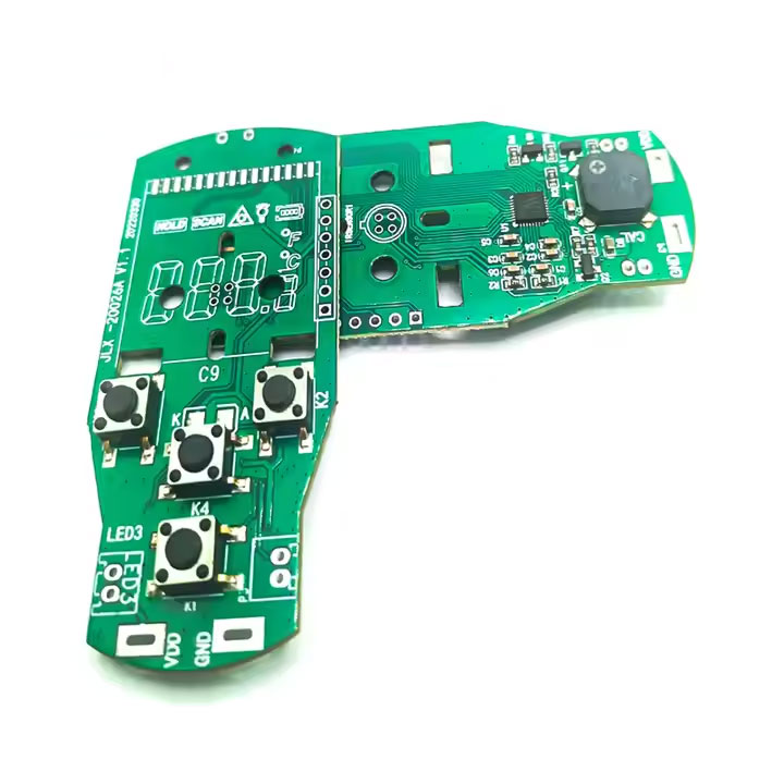
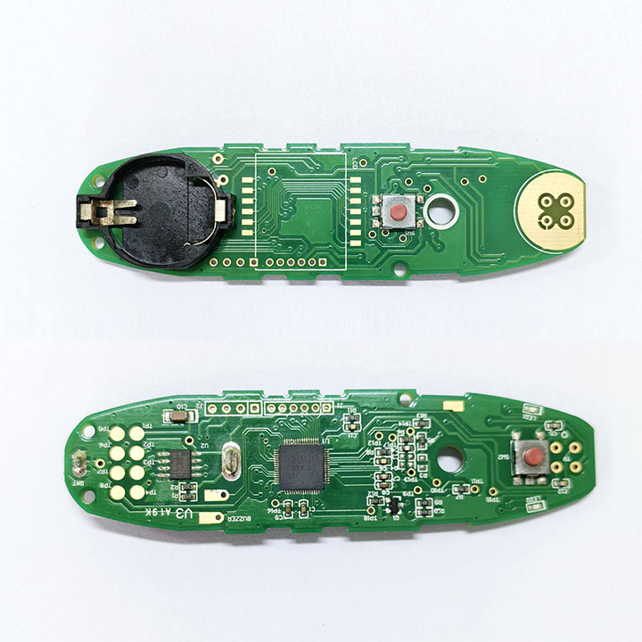
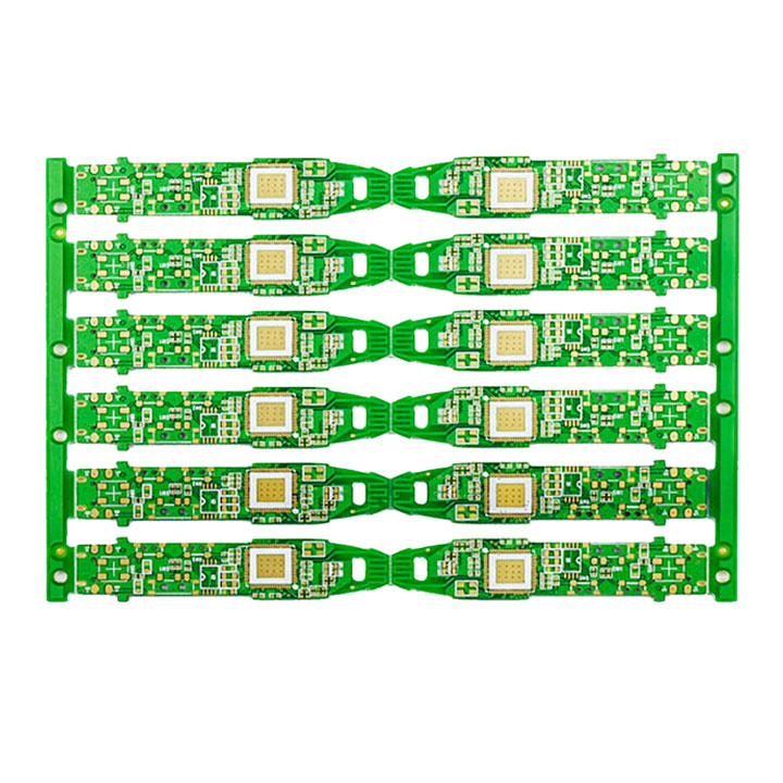
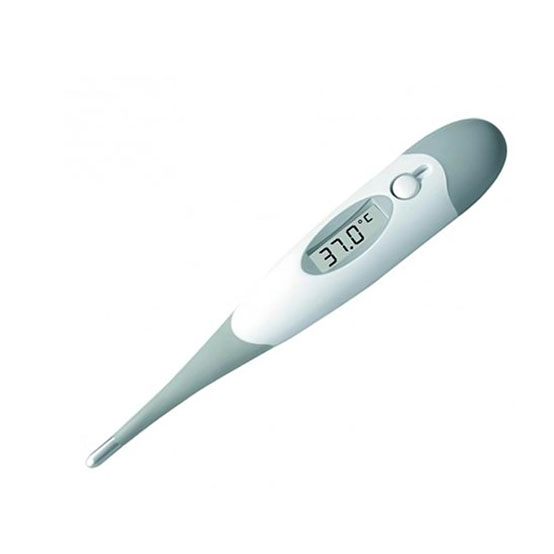
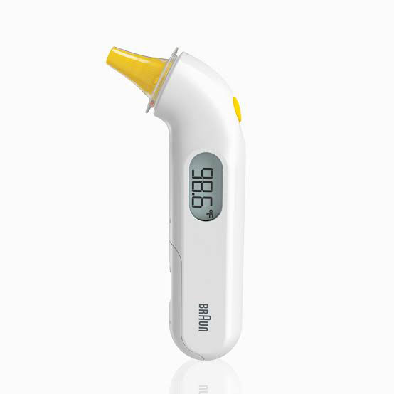
Digital thermometer PCB assembly covers three distinct signal chains built on the same manufacturing floor: NTC thermistor front-ends that measure body temperature through direct contact, infrared thermopile front-ends that measure radiated heat from the forehead or ear canal without contact, and wearable patch designs that combine a thermal sensor with a BLE SoC for continuous skin-temperature logging.
Each path fails differently. An NTC design lives or dies on reference voltage stability and PCB self-heating around the sense resistor — a layout that puts a voltage regulator too close to the thermistor divider will read high before the patient ever touches the probe. A thermopile design carries a microvolt-level signal that ambient temperature and nearby digital switching corrupt in ways that don’t show up until the unit is inside its housing. A wearable patch has to hold sealing and battery life under sweat and repeated charge cycles for weeks at a stretch. These are decisions made at DFM, not adjustments made after first article.
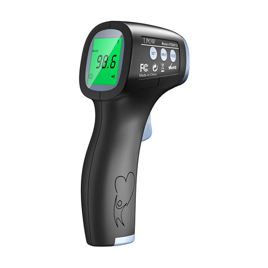
Digital Thermometer Devices We Build PCBA For
Starting from a concept, or ready to build?
Whether you are still defining the acoustic architecture or already have production files, we can support the next step of your electronic stethoscope PCBA project.
| Early-stage / NPI program | Ready-to-build program | |
| What you bring | Target accuracy spec, measurement mode, form factor | Complete Gerber, BOM, and test requirements |
| What we do | Feasibility review, sensor/architecture selection, prototype PCBA build, DFM guidance | DFM review, medical-grade PCBA assembly, functional test, documentation |
| Typical next step | Engineering discussion → prototype build → pilot run | DFM review → assembly quote → production |
| Relevant capability | NPI support, accuracy-budget review before layout is committed | ISO 13485 assembly, IPC-A-610 Class 3, regulatory-ready documentation |
If you’re at the concept stage with a target accuracy spec but no Gerber yet, send us your requirements — we review digital thermometer NPI programs and can discuss NTC vs. thermopile vs. wearable architecture before you commit to a layout.
Who builds your boards
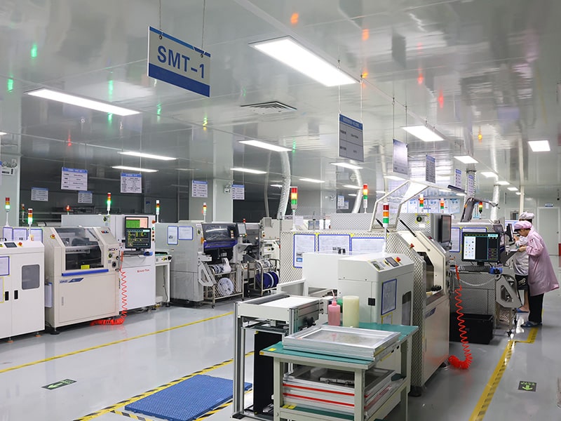
Sugamed operates a manufacturing facility with 15 Fuji and Yamaha SMT lines, 10 automatic through-hole insertion machines, multiple dedicated bonding stations, 18 PCBA assembly lines, and 40+ box-build assembly lines. Total headcount exceeds 1,100 employees.
Thermometer boards run small, low-component-count designs where a single misplaced part or process variation moves the reading outside its accuracy budget — a defect class that resistive or visual inspection alone won’t catch. Dedicated medical lines, kept separate from industrial and consumer programs, hold the process consistency this class of device depends on.
Our medical team has built PCBA across NTC, thermopile, and BLE-integrated thermometer programs, including flexible and rigid-flex wearable patches fabricated to the same PCB fabrication controls used across our diagnostic and patient monitoring device lines. ISO 13485 traceability discipline applies to component handling, assembly records, and test documentation — formatted to feed directly into DHF and regulatory submission workflows, under the same quality system that governs every medical program we run.
Where Digital Thermometer PCBA Gets Hard
Reference drift, ambient noise, sealing failure, mode crosstalk — all catchable earlier.
01 · NTC accuracy budget consumed before the probe touches skin
ISO 80601-2-56 sets a ±0.3°C laboratory accuracy limit, and every source of error in the signal chain — resistor tolerance, reference voltage drift, self-heating from a nearby regulator or digital line — draws down that budget before the patient reading happens. A board that passes a room-temperature bench test can still fail in the field once it’s warmed by its own enclosure and battery.
Reference voltage stability, resistor tolerance selection, and physical separation between heat-generating components and the sense thermistor are reviewed at DFM against the full accuracy budget, not against a generic tolerance stack. Copper pour and plane separation around the sense circuit follow the same stack-up planning discipline we apply to any noise-sensitive analog section.
02 · Thermopile signal corrupted by ambient drift and digital switching noise
A thermopile’s output sits in the microvolt range, and the co-packaged NTC used for ambient compensation only works if the compensation algorithm sees the same thermal environment the thermopile does. Add a digital switching line or a BLE transmitter on the same board, and the noise floor rises enough to shift the reading — a failure that looks like a calibration problem but is actually a layout problem.
Analog front-end gain staging, ambient-sensor placement relative to the thermopile, and ground plane separation between the analog measurement path and digital return currents are reviewed at DFM, following the same multilayer placement and routing discipline we use on RF-adjacent analog boards — before the layout is committed.
03 · Wearable patch sealing and battery life under multi-day skin contact
A continuous-monitoring patch has to survive sweat, cleaning wipes, and repeated flex without losing sensor-to-skin thermal contact or letting moisture into the analog chain. Conformal coating applied too thick insulates the sensor from the temperature it’s supposed to measure; applied too thin, moisture reaches the board within days of clinical use. Battery life on a flex board with a BLE radio is set by power sequencing decisions made at layout, not recovered later through firmware sleep modes.
Coating thickness at the sensor interface, flex-board reliability under repeated bend cycles — a construction question we evaluate against the same polyimide flex material criteria used on any flex or rigid-flex medical program — and power rail sequencing for BLE duty cycling are reviewed at DFM against the target wear duration.
04 · Multi-mode calibration crosstalk on a shared reference
A device that measures forehead, ear, and object temperature on one board shares a reference voltage and, often, a signal path across modes. A reference drift or ground bounce that’s invisible in single-mode testing can show up as a consistent bias in only one mode — a defect that single-point calibration during final test won’t surface unless each mode is verified against its own accuracy target. Fitting the extra channels and shielding into a handheld footprint is frequently where a design crosses from standard multilayer into HDI territory.
Channel isolation, per-mode calibration table validation, and shared-reference stability across all measurement modes are reviewed at DFM before the board is finalized.
Compliance & Quality Standards
Medical PCBA quality is built across three layers — the standards we manufacture under, the process checkpoints embedded in every build, and the test controls applied to TENS / EMS-specific failure modes. Each layer is set at design review, not added after first article.
Layer 1 — Standards we manufacture under
- ISO 13485 — medical device quality management system
- IPC-A-610 Class 3 — workmanship for high-reliability electronics
- IPC-J-STD-001 — soldering process compliance for medical-grade assembly
- ISO 80601-2-56 — accuracy and performance considerations integrated at DFM for clinical thermometer programs
- IEC 60601-1 / IEC 60601-1-2 — general safety and EMC behavior reviewed at design stage to support customer compliance work
Device-level certification sits with the customer. Manufacturing records are formatted to feed into DHF and regulatory submission workflows for FDA 510(k), EU MDR, and NMPA. Full certification detail is on our quality system and certifications page.
Layer 2 — Process checkpoints
① Design Review (DFM/DFT)
Accuracy budget modeling for NTC/thermopile front-ends, ambient compensation placement, BLE coexistence planning, conformal coating specification for wearable patches, and reference voltage stability review — before BOM commits. See our engineering capabilities for how DFM/DFT is run across medical programs.
② Assembly Floor
Dedicated medical lines on the same SMT assembly floor used across our diagnostic device programs. Inline AOI on every board. ESD-controlled environment throughout. Component traceability maintained at lot level.
③ Documentation
Lot-level component traceability, AOI image archives, functional test records, process validation documentation, formatted for FDA 510(k), EU MDR, and NMPA workflows.
Layer 3 — Digital thermometer-specific test controls
- Functional accuracy verification across the clinical temperature range against ISO 80601-2-56 or customer-defined targets
- Self-heating verification under representative enclosure and battery conditions
- BLE coexistence test for connected models — accuracy verified during active transmission
- Conformal coating and sealing inspection for wearable patch designs
- Per-mode calibration verification for multi-mode devices
- Battery life and low-battery cutoff verification
Related Diagnostic and Monitoring PCBA Programs
Digital thermometers share manufacturing floor, quality system, and often BLE architecture with other diagnostic and patient monitoring devices we build:
- Electronic Stethoscope PCB Assembly
- Portable Ultrasound PCB Assembly
- Pulse Oximeter PCB Assembly
- Blood Pressure Monitor PCB Assembly
- ECG Patch PCB Assembly — a comparable wearable, sealed-patch build for continuous monitoring
- Patient Monitor PCB Assembly
FAQ
What’s the typical lead time for a thermometer prototype?
Prototype builds typically run 3–5 weeks from Gerber receipt through functional test, depending on component availability.
Can you support the transition from prototype to volume production?
Yes. Process records and inspection criteria established at prototype carry forward through low-volume pilot runs into turnkey volume production — no requalification when scaling.
Do you test accuracy against ISO 80601-2-56, or is that the customer’s responsibility?
We build and execute the accuracy test against your specification or ISO 80601-2-56 targets; we do not hold device-level certification. Test protocol and pass/fail criteria are agreed at DFM.
How do you handle sealing on wearable patch designs?
Coating thickness and sealing method are reviewed at DFM against the target wear duration and cleaning agent exposure, using flex/rigid-flex construction where the form factor requires it, then verified at first article — not left to a generic conformal coating default.
What compliance documentation do you provide with each build?
Lot-level traceability, AOI image archives, functional test records, process validation documentation, and material certificates, formatted for FDA 510(k), EU MDR, and NMPA workflows. See our quality system certifications for the full standards list.
Do you support box-build and complete device assembly?
Yes. Sugamed operates 40+ box-build assembly lines through our turnkey PCB assembly service, covering PCBA assembly plus housing, probe, and packaging integration within one workflow.
Start your Digital Thermometer PCBA project
Quote from our medical PCBA engineers within 24 hours.