
A rigid-flex board asks more of its materials than a rigid-only design does. Each material in the stack still has to meet the usual electrical and manufacturing requirements, but it also has to survive being bent — once during assembly, or thousands of times in service, depending on the design. That extra requirement changes which properties actually matter when a material gets chosen. Static and dynamic flex applications don’t weigh those properties the same way, and bend type is the first thing worth settling before working through the choices below. This article covers how rigid laminate, polyimide flex substrate, copper foil, coverlay or flexible solder mask, and bonding materials get selected against each other — not how they’re sequenced into a layer stack, how the board is fabricated, or how flex reliability is validated through bend and thermal cycling.
Table of contents
Rigid Laminate and Polyimide in the Same Construction
The rigid sections of a rigid-flex board use the same epoxy-glass laminate as any standard multilayer PCB — FR4 or a higher-performance variant, chosen on the usual electrical, thermal, and cost grounds that apply to rigid design. Nothing about that decision changes because the board also has a flex section.
The flex sections use polyimide film instead, and not because polyimide offers some electrical advantage over FR4. It’s chosen because it tolerates repeated flexing without cracking, holds up across a wide temperature range, and stays dimensionally stable through the lamination cycles the board goes through. The rigid and flex material families don’t need to match each other electrically — they need to bond reliably and behave predictably at the point where one turns into the other.
Adhesive-Based vs. Adhesiveless Flex Laminate
Flex laminate — the copper-clad polyimide that the flex circuit is etched from — comes in two constructions. Adhesive-based laminate bonds copper foil to the polyimide film with a separate adhesive layer, usually acrylic or modified epoxy. Adhesiveless laminate skips that layer at this specific interface: copper is deposited or cast directly onto the polyimide, so there’s no distinct adhesive bondline between foil and film.
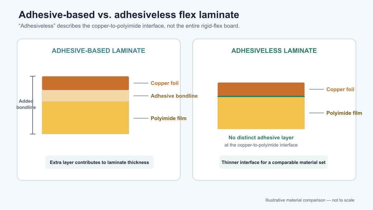
Removing that layer makes the laminate thinner and more dimensionally stable at that interface, and it can improve thermal performance there, since adhesive layers tend to have a lower thermal tolerance than the copper and polyimide around them. A thinner cross-section also tends to tolerate a tighter bend radius for a given strain, which is why adhesiveless laminate shows up more often in designs that flex continuously in service.
It’s worth being precise about what “adhesiveless” actually means here: it describes the copper-to-polyimide bond within the flex laminate itself, not the entire rigid-flex construction. Coverlay still bonds to the flex circuit with its own adhesive, and bondply or no-flow prepreg still bond the flex core into the rigid substack. An adhesiveless laminate doesn’t remove adhesive from the rest of the board.
Adhesive-based laminate remains a reasonable choice where the flex section only folds once or twice during assembly and stays static afterward. It’s more widely stocked across foil weights and polyimide thicknesses, which can matter for cost and lead time on designs where dynamic fatigue life isn’t the deciding factor.
RA vs. ED Copper Foil in Flex Regions
Copper foil for flex circuits comes in two forms with different internal grain structures. Rolled annealed (RA) copper is mechanically rolled and annealed, which elongates and aligns its grain structure in the rolling direction. That alignment gives it better fatigue resistance under repeated flexing than electrodeposited (ED) copper, whose grain structure forms as columnar or nodular grains during electroplating — a structure that tends to crack sooner under the same repeated bending.
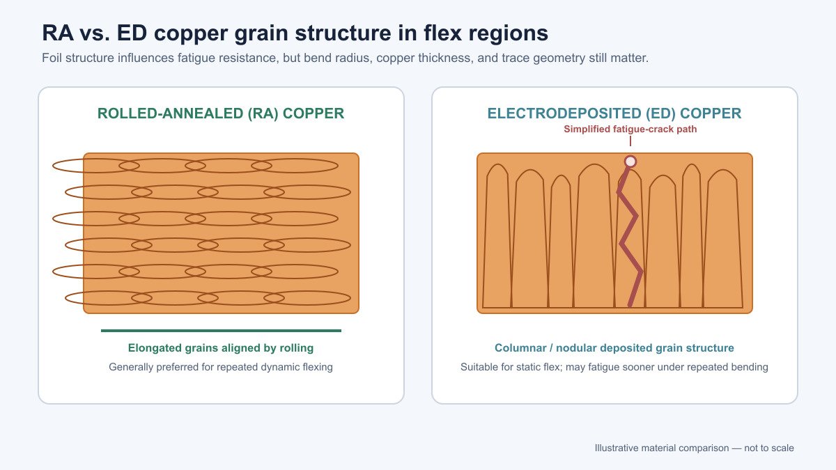
ED copper is the standard foil for rigid PCBs and costs less, so it’s the default many fabricators reach for unless the flex application specifically calls for RA. That default works fine for static flex regions that see one fold or occasional handling. Dynamic flex regions — anywhere the board bends repeatedly through its service life — are where the fatigue difference between RA and ED copper actually shows up, which is why RA copper is the more common choice for that use case.
Foil type isn’t the only variable behind bend fatigue, though. Copper thickness, trace width and any abrupt width changes that act as stress risers, and the bend radius the design actually holds to all affect fatigue life independently of whether the foil is RA or ED. A dynamic design built with RA copper but routed with sharp trace transitions or bent tighter than the material tolerates can still fail early — foil selection addresses one part of the fatigue picture, not all of it.
Coverlay vs. Flexible Solder Mask
Coverlay is a polyimide film with its own adhesive layer, laminated over the etched flex circuit with openings already cut for pads, connectors, and any other spot that needs exposed copper. It protects the copper the same way solder mask does on a rigid board, but it has to keep doing that job through however much bending the flex section sees.
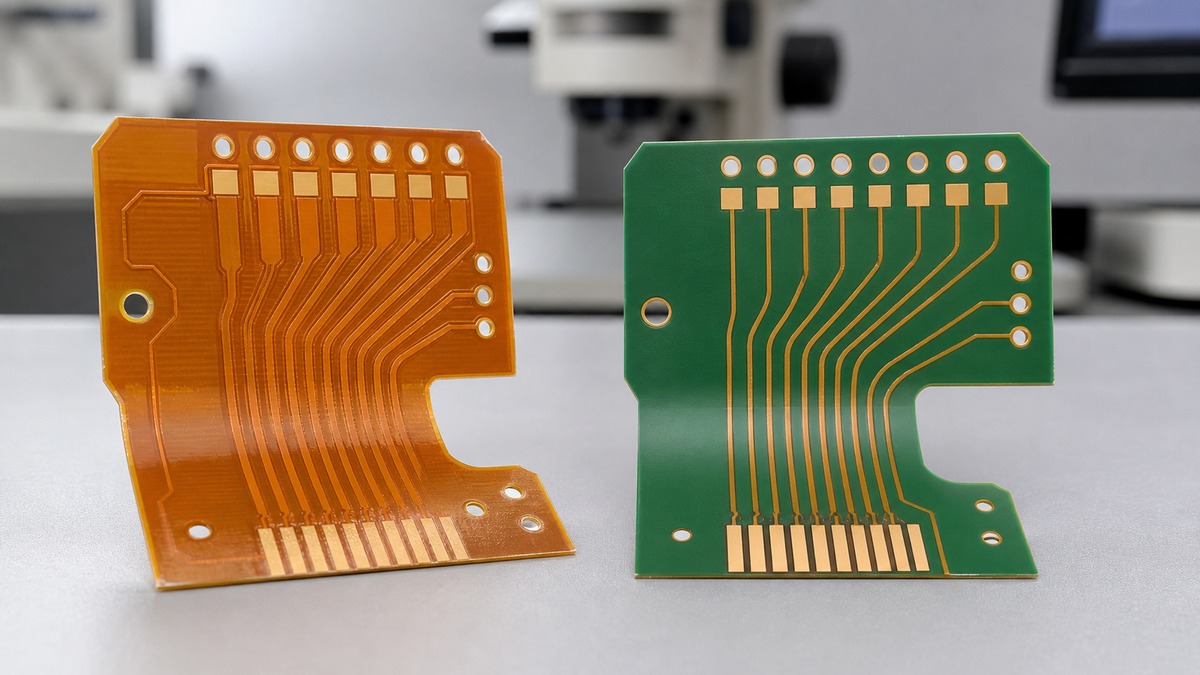
Flexible solder mask is a liquid photoimageable mask formulated to stay flexible after cure, applied the same way rigid solder mask is — no separate lamination step, no pre-cut film to align. That can simplify processing and reduce cost compared to coverlay lamination, particularly where opening geometry is dense or irregular enough that registering pre-formed coverlay openings is harder than photoimaging a mask pattern directly.
Where flexible solder mask fits is narrower than where coverlay fits. It can be workable on static or lightly-flexed sections, or in areas where the mechanical demands on the protective layer are modest. Coverlay remains the more established choice for dynamic bend zones and anywhere long-term flex durability is a firm requirement — its adhesion and thickness behavior through repeated bending is better established than flexible solder mask’s, and the difference is worth confirming against the specific flex duty cycle rather than assumed either way. Thickness control is also more consistent with coverlay, since it’s a fixed film rather than a cured liquid coating, and opening tolerance depends on how the film is cut rather than on photoimaging resolution.
Stiffener material is a related but separate choice. It’s added outside the bend area to give local rigidity for connectors or components, and it’s selected on assembly and support grounds — FR4, polyimide, or stainless steel are common options — rather than on flex fatigue grounds, since it doesn’t sit in the flexing section itself.
Bondply and No-Flow Prepreg: Resin Flow, Thickness, and Compatibility
Bondply and no-flow prepreg are both adhesive materials used to bond layers together, and choosing between them — or between different formulations of each — comes down to resin behavior rather than where the bond sits in the stack. That structural placement question belongs to stackup design; this is about what the resin itself needs to do.
Standard prepreg resin flows under heat and pressure during lamination, which is exactly what’s needed when bonding two rigid layers together but a problem when a flex area sits nearby, since flowing resin can bleed into it and stiffen material that’s supposed to stay flexible. No-flow and low-flow prepreg formulations are built to minimize that bleed, at the cost of somewhat less gap-filling ability than standard prepreg — a tradeoff that matters more on designs with uneven copper distribution near the flex boundary.
Bondply is an unreinforced B-stage adhesive film, typically acrylic or epoxy-based, used where a bond doesn’t need to fill around copper features the way prepreg does. Selecting one bondply over another is mostly a compatibility and cure-profile question: the adhesive chemistry has to bond well to polyimide and to whatever coverlay adhesive it sits against, and its cure temperature and pressure need to fit within the same lamination cycle as everything else in the stack. Compatibility and cure profile matter more here than the specific brand or grade: a resin system that isn’t compatible with the adjacent adhesive chemistry, or that cures at a temperature the rest of the stack can’t tolerate in one pass, can cause bond failures that no amount of care with product selection elsewhere in the stack will fix.
Every added bonding layer adds thickness, but the decision at this stage is about resin flow, cure compatibility, and thermal rating — not about how much of that thickness the final stackup can absorb, which is a separate calculation once the material list is set.
Material Selection by Bend Type, Temperature, and Thickness
Put together, these material choices sort fairly cleanly by how the flex section is actually used. Dynamic flex applications push toward adhesiveless laminate, RA copper, and coverlay, because fatigue life under repeated bending is the constraint that dominates everything else. Static or single-fold applications have more room to work with — adhesive-based laminate, ED copper, and even flexible solder mask can all be acceptable there, and cost or lead time often becomes the bigger factor once fatigue life stops being the limiting concern.
Temperature exposure narrows the adhesive and resin choices further. The lamination cycle itself sets a floor, since every adhesive in the stack has to survive it, but downstream exposure matters too — reflow soldering during assembly, or a high operating temperature in service, can push a design toward adhesive systems with a higher thermal rating even when the flex duty cycle alone wouldn’t require it.
Thickness is the thread that runs through every choice above. Adhesiveless laminate, coverlay versus flexible solder mask, and the bonding materials all add up to a total thickness in the flex region, and that thickness relates directly to the bend radius the section can hold without overstressing the materials in it — thinner constructions generally tolerate tighter bends. Surface finish selection (ENIG, immersion silver, and similar options) follows the same criteria it would on a rigid board — assembly process, shelf life, connector requirements — and doesn’t materially change any of the bend-related choices above.
None of this replaces validating the final material combination through actual bend and thermal cycling, which is a separate topic. But bend type, temperature exposure, and accumulated thickness are the three factors that should be driving the material list in the first place — get those settled, and the individual choices between adhesive types, foil grain structure, and protective coatings stop being open questions and start being straightforward fits to a known requirement.