
Medical PCB Assembly for Medical Electronics
Home » Medical PCB Assembly
We provide safe and reliable medical PCB assembly services for diagnostic, monitoring, rehabilitation, and therapeutic medical devices.
Supports prototype and low-volume medical PCB assembly, with turnkey sourcing, fine-pitch SMT, BGA assembly, and in-process inspection from SPI to X-ray.
- 15 SMT Production Lines
- 01005 Components
- 0.35 mm Pitch BGA
- SPI · AOI · X-Ray
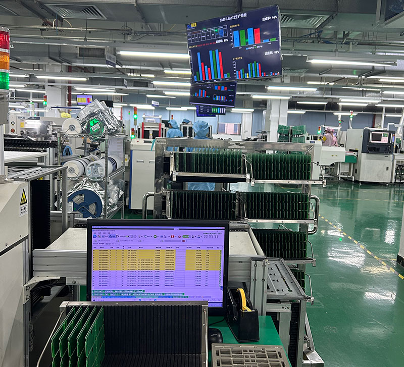
Medical electronics often move through several manufacturing stages before a design becomes stable—from engineering prototypes and first article builds to design revisions, pilot production, and repeat low-volume orders. Each stage places different demands on PCB assembly, documentation, inspection, and change control.
SugaMed supports medical electronics projects with prototype, low-volume, and turnkey PCB assembly, backed by fine-pitch SMT, BGA assembly, mixed-technology production, and inspection integrated throughout the assembly process.
Our China manufacturing facility operates 15 SMT production lines, providing production capacity for projects ranging from early engineering builds to repeat low-volume manufacturing.
Medical PCB Assembly Services
A medical device project may require more than one type of PCB assembly support during its product lifecycle. An early engineering build, a recurring low-volume order, and a project requiring full material sourcing do not necessarily follow the same manufacturing workflow.
Our medical PCB assembly services cover different production stages and service models.
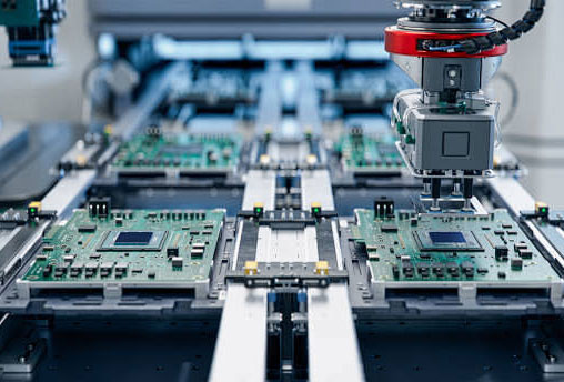
Assembly support for early engineering builds, design verification, and medical electronics projects that may require changes before moving into low-volume production.
- Engineering Prototype Builds
- DFM and Assembly Review
- First Article Verification
- Support for Design Revisions
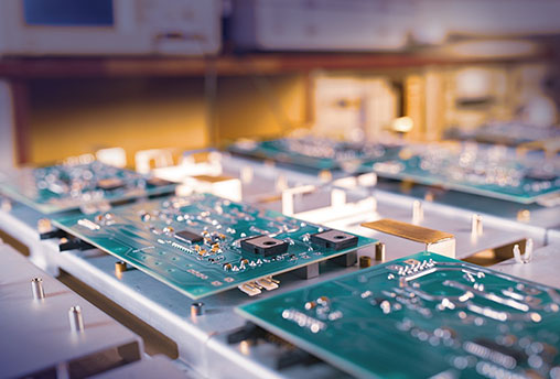
Flexible assembly support for pilot runs, recurring small-batch orders, and medical electronics projects with multiple PCB models or ongoing design revisions.
- Pilot Runs & Repeat Orders
- Small-Batch, Multi-Model Production
- PCB and BOM Revision Control
- Production and Inspection Records
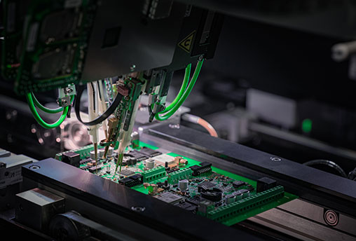
Coordinated PCB assembly support covering PCB fabrication, component sourcing, assembly, and inspection through a single project workflow.
- PCB Fabrication Coordination
- BOM and Component Sourcing
- SMT and Through-Hole Assembly
- Inspection and Testing Support

SMT assembly for medical electronics using automated solder paste printing, fine-pitch component placement, controlled reflow, and in-process inspection.
- 01005 Component Capability
- Fine-Pitch QFN & BGA Assembly
- SPI and AOI Inspection
- Double-Sided SMT Assembly
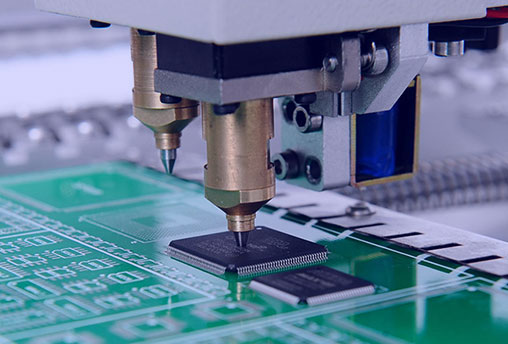
Assembly and inspection support for BGA and other complex packages with solder joints that cannot be fully evaluated through visual inspection alone.
- 0.35 mm Pitch BGA Capability
- Controlled Placement and Reflow
- X-Ray Inspection
- BGA Rework Support
SMT and Assembly Capabilities for Complex Medical PCBAs
Our SMT lines support fine-pitch components, complex PCB structures, mixed-technology assembly, and medical electronics projects at different production stages.
Manufacturing Scale
SMT production lines in China
Max Board Size
Supported PCB Layer Count
Component and Board Capability
Our SMT equipment supports miniature passive components, fine-pitch IC packages, large connectors, and a range of rigid, flex, rigid-flex, and HDI PCB designs.
01005 (0.4 × 0.2 mm)
0.35 mm
0.35 mm
0.4 mm
45 × 45 mm
45 × 100 mm
Rigid, Flexible, Rigid-Flex, HDI, High Tg, and RF
±0.035 mm for Chip Components ±0.025 mm for IC Packages
Supported Assembly Processes
Our assembly lines support multiple process routes for medical electronics that combine surface-mount components, through-hole parts, flexible circuits, and components with different soldering requirements.
SMT and through-hole assembly on the same board
Reflow soldering for compatible through-hole components
Component placement and reflow on both PCB sides
Two-sided SMT followed by through-hole soldering
Controlled handling and tooling for flexible circuits
Process Control & Inspection
From solder paste printing to final inspection, key assembly stages are checked before the PCBA leaves the production line.
Solder Paste Printing
3D SPI
Component Placement
Reflow
3D AOI
First Article Inspection
X-Ray When Required
Board Unloading
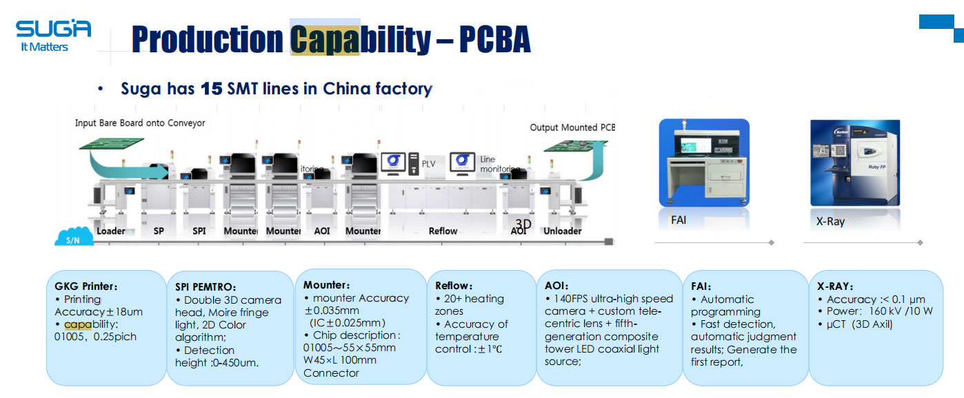
Stage 1: Solder Paste Printing & SPI
Capability data
- Printing Accuracy: ±18 μm
- Minimum Component: 01005
- SPI: 3D Inspection
- Inspection Height: 0–450 μm
Stage 2: Component Placement & Reflow
Components are placed using automated SMT equipment and soldered through a controlled reflow process matched to the PCB and component mix.
Capability data
- Chip Placement Accuracy: ±0.035 mm
- IC Placement Accuracy: ±0.025 mm
- Component Range: 01005 to 55 × 55 mm
- Maximum Connector Size: 45 × 100 mm
- Reflow: 20 Heating Zones
- Temperature Control: ±1°C
Stage 3: AOI & First Article Inspection
3D AOI checks visible placement and soldering conditions after reflow. First article inspection provides an additional verification point for new or revised builds.
Capability data
- AOI Speed: Up to 140 Frames per Second
- Inspection: Multi-Angle Optical Inspection
- FAI Programming: Automated
- FAI Reports: Automatically Generated
Stage 4: X-Ray Inspection
X-ray inspection is used for BGAs, QFNs, and other packages with hidden solder joints when required by the component type or inspection plan.
Capability data
- X-Ray Source: 160 kV / 10 W
- Inspection Mode: 2D X-Ray and 3D Micro-CT
- Applications: BGA, QFN, and Hidden Solder Joints
- Inspection Coverage: Defined by Project Requirements
Medical PCB Assembly Controls
Medical electronics projects often involve multiple builds, design revisions, and project-specific documentation requirements. These controls help keep materials, manufacturing data, inspection requirements, and production records aligned throughout the project.
01
Material and Component Traceability
Traceability requirements are defined according to the project scope. Where required, PCB, component, material, and production-lot information is recorded so that the materials used in a specific build can be referenced later.
Records may include:
- PCB lot identification
- Component lot or date-code information
- Material and production batch records
- Project-specific traceability documentation
02
First Article and Build Verification
New or revised PCB assemblies can undergo first article review before repeat production continues. This provides an additional verification point for confirming that the released manufacturing data has been applied correctly.
Verification may include:
- PCB and BOM revision confirmation
- Component placement
- Polarity and orientation
- Assembly and inspection requirements
03
PCB and BOM Revision Control
Production is based on the current approved PCB files, BOM, pick-and-place data, and assembly drawings. Superseded files are separated from the released production package to reduce the risk of outdated information being used in a later build.
Controlled documents include:
- PCB fabrication files
- Approved BOM revision
- Pick-and-place data
- Assembly drawings and work instructions
04.
Production and Inspection Records
Production and inspection records can be maintained according to the agreed project requirements. These records provide a reference for repeat builds, engineering reviews, and subsequent quality investigations where needed.
Available records may include:
- Production batch information
- First article inspection records
- SPI, AOI, and X-ray inspection results
- Electrical or functional test records where applicable
From Prototype Build to Low-Volume Production
Medical electronics projects often require several builds before the design and manufacturing data become stable. This four-stage workflow connects project review, prototype assembly, first article verification, and low-volume production under controlled revisions and inspection requirements.
Project Review
Send your Gerber files, BOM, pick-and-place data, assembly drawings, target quantity, and inspection or testing requirements. We review the project package for missing information, assembly risks, component concerns, and manufacturing requirements before quotation and build planning.
Prototype Build
Prototype boards are assembled using the SMT, reflow, and inspection processes planned for later production. Initial assemblies can undergo first article review to confirm component placement, polarity, soldering conditions, and the released manufacturing data.
First Article and Changes
First article results and manufacturing feedback are reviewed before the next build. Approved changes to the PCB, BOM, components, drawings, or inspection requirements are incorporated into the current production package.
Low-Volume Production
Once the design and manufacturing data are stable, the project can move into pilot runs, recurring small-batch orders, or multi-model low-volume production using revision-controlled files and agreed production and inspection records.
Turnkey PCB fabrication and component sourcing can be included at any stage where required.
Medical Electronics Applications We Support
We provide PCB assembly for patient monitoring, therapeutic, diagnostic, and portable medical electronics. Manufacturing and inspection processes are planned according to each project’s PCB structure, component packages, production stage, and testing requirements.
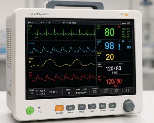
Patient Monitoring Devices
PCB assembly for medical electronics that acquire, process, display, or transmit patient data. These projects may involve sensor interfaces, signal-processing circuits, wireless communication, compact layouts, and multiple design revisions.
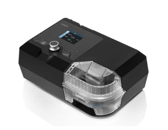
Therapeutic Device PCBAs
Assembly support for electronically controlled therapeutic equipment that may combine sensing, power management, pump or motor control, communication, and user-interface circuits within the same product.
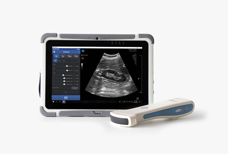
Diagnostic Device PCBAs
PCB assembly for diagnostic and portable medical electronics where board size, battery operation, component density, connectors, and inspection requirements must be considered together.
Frequently Asked Questions
What is medical PCB assembly?
Medical PCB assembly is the process of mounting and soldering electronic components onto printed circuit boards used in medical devices and related healthcare electronics. Depending on the project, it may include SMT, through-hole assembly, BGA assembly, programming, inspection, and functional testing.
Compared with general PCB assembly, medical electronics projects often require clearer control of approved revisions, component traceability, inspection records, testing responsibilities, and acceptance criteria. Manufacturing may be performed within an ISO 13485-certified quality management system, while the applicable IPC-A-610 class and workmanship requirements should be defined for each project.
These assemblies may be used in patient monitoring, therapeutic, diagnostic, and portable medical electronics.
Does every medical PCB assembly require IPC Class 3?
No. The required IPC class depends on the intended use of the product, reliability requirements, risk assessment, and contractual requirements.
Some medical electronics may be assembled to IPC Class 2, while higher-reliability products may require Class 3. The required class should be stated in the approved project documentation.
Does ISO 13485 mean that a PCBA complies with IEC 60601?
No. ISO 13485 applies to the manufacturer’s quality management system. IEC 60601 applies to the safety and essential performance of complete medical electrical equipment.
An ISO 13485-controlled assembly process can support the medical device manufacturer’s quality requirements, but it does not independently demonstrate IEC 60601 compliance for the finished product.
What are your typical PCB assembly lead times?
Lead time depends on PCB complexity, order quantity, component availability, fabrication requirements, inspection scope, and testing needs. Production lead time normally begins after the manufacturing files have been approved and all required PCBs and components are ready.
- Prototype PCB Assembly: Simple assemblies typically require 5–7 business days. Complex builds involving fine-pitch components, BGAs, special materials, mixed assembly processes, or additional testing may require approximately 2–4 weeks.
- Low-Volume PCB Assembly: Typically 2–4 weeks after materials and approved manufacturing files are ready. Repeat orders may be completed sooner when components are available and the production process has already been established.
- Turnkey PCB Assembly: Typically 4–8 weeks, depending on PCB fabrication, component sourcing, and testing requirements. Long-lead or obsolete components may extend the schedule.
- Assembly-Only SMT Projects: Typically 7–15 business days after the PCBs, components, and approved files are ready.
- BGA Assembly: Usually follows the lead time of the main PCB assembly order. Additional time may be needed for BGA rework, detailed 3D CT inspection, or failure analysis.
These estimates refer to production at our Dongguan facility and do not include international shipping or customs clearance. Shipping time is quoted separately according to the destination, shipment size, and selected delivery method.
Can you review a project if some files are incomplete?
Yes. You can submit the files currently available for an initial review.
The review may identify missing, outdated, or conflicting information. Production should not be released until the required PCB data, BOM, placement data, drawings, revisions, and manufacturing instructions have been confirmed.
How are alternative components handled?
Alternative components are not introduced without customer review and approval.
When the specified part is unavailable, a possible replacement can be reviewed for electrical compatibility, package fit, lifecycle status, temperature range, availability, and potential impact on product verification.
What is required for functional testing?
Functional testing normally requires:
- An approved test procedure
- Defined pass-and-fail criteria
- Test fixtures and cables
- Required software or firmware
- Programming instructions
- A reference unit where applicable
- Instructions for recording and handling failures
Testing responsibilities and expected reports should be agreed during project review.
Can you take over a project from another PCB assembly supplier?
Yes, but the transferred manufacturing package should be reviewed before production resumes.
Useful information may include:
- Current PCB and BOM revisions
- Approved component substitutions
- Assembly drawings
- Programming files
- Test procedures and fixtures
- Previous manufacturing issues
- Inspection and production records
A first article build is generally advisable before recurring production begins with the new supplier.
What records can be provided with the order?
Available records depend on the agreed project scope.
They may include:
- Production batch information
- Material or component traceability records
- First article inspection records
- SPI, AOI, or X-ray results
- Electrical or functional test records
- Approved revision information
Required records should be confirmed before quotation so that the manufacturing and documentation plan can be prepared accordingly.
Ready to get started on your project?
Whether you’re evaluating us for a new project or transitioning from another supplier — the starting point is a direct conversation with our engineering team.
Discuss Your Project
Share your board complexity, volumes, and regulatory requirements. We'll give you a clear picture of what we can do and what the timeline looks like.
Schedule a Facility Visit
On-site visits to our Dongguan facility can be arranged — production floor access, quality system review, and time with engineering team leads.
Before You Start a Medical PCB Assembly Project
A successful medical PCB assembly project requires more than Gerber files and a BOM. Defining the manufacturing, inspection, testing, and documentation requirements early helps reduce unexpected costs, production delays, and unclear compliance responsibilities.
Define the Project Requirements
Two medical devices using similar components may still require very different manufacturing controls. Before production begins, the released project package should clearly identify:
- Current revisions of the PCB files, BOM, and assembly drawings
- Build stage and quantity, such as prototype, pilot, or repeat production
- Workmanship and acceptance criteria
- Component and material traceability requirements
- Inspection and testing responsibilities
- Required production and quality records
- Approval processes for substitutions and design changes
- Special cleaning, coating, programming, or packaging requirements
Not every medical PCBA requires the same controls. The priority is to define the applicable requirements clearly and include them in the approved manufacturing package.
Medical PCB Assembly Standards
Several standards may apply to a medical electronics project, but they address different parts of the manufacturing and product-compliance process. The applicable standard, revision, class, and customer-specific requirements should be confirmed before quotation and production.
ISO 13485
ISO 13485 defines quality management system requirements for organizations involved in medical devices and related services. For PCB assembly projects, it may support document control, traceability, supplier management, change control, corrective action, and production record retention.
It does not define whether an individual solder joint or completed electronic assembly is acceptable. Separate workmanship and acceptance criteria are still required.
IPC-A-610 and J-STD-001
IPC-A-610 provides acceptance criteria for completed electronic assemblies, while J-STD-001 addresses soldering materials, processes, and workmanship requirements.
The customer and PCB assembly manufacturer should agree on the applicable revision and product class. Not every medical PCB assembly project automatically requires IPC Class 3, and any project-specific exceptions should be documented.
IEC 60601
IEC 60601 addresses the basic safety and essential performance of medical electrical equipment.
PCB design and assembly quality can contribute to the finished product’s compliance, but a PCBA alone does not demonstrate that the complete medical device complies with IEC 60601. Product-level compliance remains the responsibility of the medical device manufacturer.
Choose the Right PCB Construction
PCB construction should follow the device’s electrical, mechanical, thermal, environmental, and space requirements. Selecting a more complex PCB technology does not automatically improve the product and may add unnecessary manufacturing cost.
Rigid PCBs
Rigid PCBs are commonly used for fixed, enclosure-mounted electronics. The material, copper weight, layer count, thickness, surface finish, and thermal requirements should be selected according to the circuit and operating environment.
Flex and Rigid-Flex PCBs
Flex and rigid-flex PCBs can support compact layouts, three-dimensional installation, and connections between board sections without separate wiring.
Assembly planning should consider support fixtures, flexible-area handling, component placement restrictions, panel stability, and movement during printing and reflow. Bend areas and rigid-flex transition zones also require appropriate design controls.
HDI PCBs
HDI structures may be required for compact medical electronics using fine-pitch components, microvias, dense routing, or reduced board area.
The stack-up, via structure, pad design, surface finish, component pitch, and inspection access should be reviewed together. A PCB that can be fabricated successfully is not necessarily easy to assemble, inspect, or rework.
High-Tg and RF Materials
High-Tg laminates may be appropriate where processing temperatures, operating temperatures, or thermal cycling require greater material stability. RF and low-loss materials may be needed for wireless communication, sensing, imaging, or other high-frequency circuits.
Materials should be selected according to actual product requirements rather than the highest specification available.
Decisions Before Production
Several decisions directly affect the assembly process, quotation, inspection plan, and documentation package. These requirements should be clarified before materials are purchased or the build is released.
Acceptance Criteria
Define the applicable IPC class, workmanship standard, cosmetic requirements, customer-specific acceptance criteria, and approved deviations.
The term “medical grade” alone does not provide enough information for the assembly manufacturer to determine the required product class or inspection standard.
Traceability
Traceability may range from basic production-batch identification to detailed records covering PCB lots, component lots, manufacturer date codes, material batches, production revisions, inspection results, and test results.
The required level of traceability and the record-retention period should be agreed before sourcing and production begin.
Testing
The customer and manufacturer should define the required inspection and test methods, together with responsibility for each activity. These may include visual inspection, SPI, AOI, X-ray inspection, flying probe testing, ICT, programming, functional testing, or calibration.
Functional testing normally requires an approved test procedure, suitable fixtures and cables, the necessary software or firmware, defined pass-and-fail criteria, and instructions for recording and handling failures.
Cleaning and Protective Coatings
Some assemblies may require controlled cleaning, ionic contamination testing, conformal coating, potting, underfill, moisture protection, or special ESD handling.
Where these processes apply, the documentation should define the approved materials, application areas, masking requirements, curing conditions, inspection criteria, and any rework restrictions.
Component Substitutions
A replacement component should not be approved solely because it fits the same footprint.
The review may also need to consider electrical characteristics, package and pin compatibility, temperature rating, lifecycle status, manufacturer qualification, software or firmware interaction, and potential impact on product verification.
Alternative components should only enter production after completing the agreed customer approval process.