Medical Device PCBA

Pulse Oximeter PCB Assembly

Medical-grade SpO2 PCBA for fingertip, handheld, wearable, and OEM pulse oximeter applications.

The Engineering Reality Behind Pulse Oximetry

PPG signal chain block diagram for pulse oximeter PCB design

Pulse oximeters are everywhere in modern healthcare. ICU bedside monitors, handheld spot-check devices in ambulances, fingertip units on every nurse’s station, and a growing wave of wearable rings and patches aimed at the remote monitoring market. On paper, the devices look simple — a few LEDs, a photodiode, a small board. In practice, they’re one of the harder things to build well.

The reason is the signal itself. What the photodiode produces is a tiny photocurrent, usually in the nanoampere range, riding on top of a DC baseline that’s orders of magnitude larger. Any noise that couples into that path — from the LED drive currents, from nearby digital switching, from ambient light leaking in — shows up directly in the SpO2 reading. There’s no firmware trick that fully cleans up a noisy front-end.

So when we talk about pulse oximeter PCBA, we’re really talking about signal integrity discipline applied to medical optical sensing. It’s not the same problem as building a consumer wearable, even if the bill of materials looks similar.

Pulse Oximeter PCBA We Build

Most of our pulse oximeter work falls into five form factors. Each has its own design priorities and its own set of manufacturing gotchas.

Fingertip pulse oximeters.​

Small rigid boards, usually four layers, with an OLED driver and an ultra-low-power MCU. Coin-cell powered in most cases. Volume-friendly, and the segment where manufacturing cost discipline matters most.

Handheld and spot-check oximeters.​

A size up from fingertip — LCD displays, rechargeable Li-Po, and usually a USB or serial interface for data logging. Common in ambulance kits and clinical spot-check carts.

Wearable oximeters — rings, wrist units, and patches.​

This is the segment growing fastest right now, and also the hardest to build well. Flexible or rigid-flex PCB assembly, BLE integration, and battery life as the headline spec. Every decision downstream of "make it small and make it last" gets shaped by that constraint.

Neonatal and pediatric oximeters.​

Reflectance-mode optical interfaces, low-saturation accuracy requirements, and very compact form factors. Lower volume, higher complexity, and usually tighter regulatory scrutiny because the patient population is vulnerable.

OEM SpO2 module boards.​

Embeddable modules with standardized UART or I2C interfaces, built to be integrated into multi-parameter monitors, ventilators, or other larger medical systems. Different buyer, different design brief — the customer is usually an integration engineer, not a product manager.

What Actually Matters in PPG Signal Chain Manufacturing

This is the part most contract manufacturers either skip or summarize in one line. It’s also where pulse oximeter projects usually get into trouble.

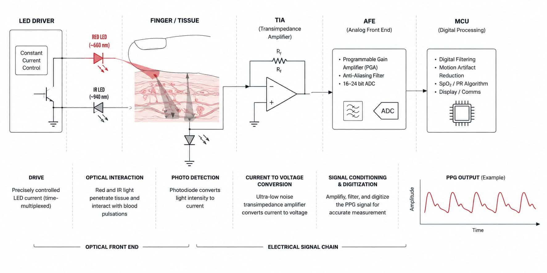
LED drive and optical front-end

The LEDs pulse hard and fast — high peak currents with short on-times. The dI/dt on the drive return path is substantial, and if that return path shares copper with the photodiode signal path, you’ll see the LED switching show up directly in the PPG waveform. Every time. It’s one of the most common problems we see on incoming designs that didn’t go through a proper DFM review.

The fix isn’t complicated in principle: physically separate the LED drive loop from the photodiode receive loop, keep return currents tight, and don’t be clever about saving copper in the wrong place. But it has to be done at layout time, not patched in later.

Analog front-end layout

Whether the design uses an integrated SpO2 AFE IC or a discrete trans-impedance plus filter chain, the priorities are the same. Low-noise analog supply, short and symmetric signal traces, and minimized coupling between the switching digital domain and the sensitive analog side.

Honestly, most of what goes wrong here isn’t exotic. It’s decoupling caps placed slightly too far from the IC pin, or an analog ground pour that got broken up by a digital trace someone routed through it at the last minute. Small things, big effect on final signal quality.

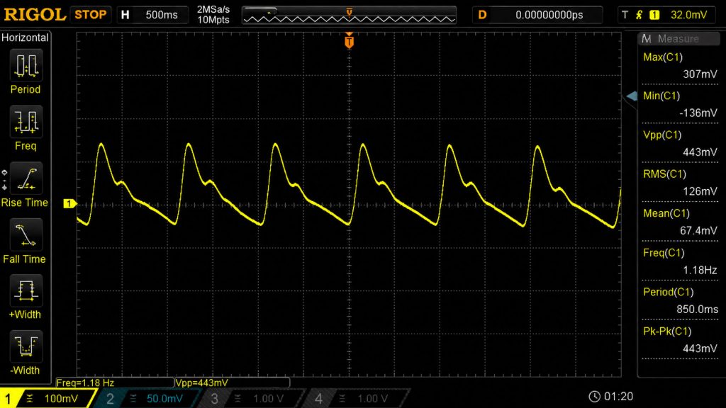
During pilot runs, we usually validate baseline noise and PPG waveform stability before releasing the build into production.

Oscilloscope-Waveform-Capture


Motion artifact and ambient light rejection

These are firmware features, but the board has to cooperate. The LED pulse timing and photodiode sampling window have to stay clean — no phase noise creeping in from a dirty clock tree, no unexpected ground bounce during the dark-frame subtraction interval. If the hardware doesn’t hold still, the algorithm can’t do its job.

Mixed-signal discipline

Analog and digital ground partitioning with single-point connection. Controlled impedance where it matters. Star topology for the sensitive supply rails. The usual things — applied with pulse oximeter signal integrity in mind, rather than borrowed wholesale from a consumer electronics playbook.

Ultra-low-power work for wearables

For wearable oximeters, battery life is almost always the spec that kills or saves the product. We validate sleep-mode current against the design target before the first production run — because finding out three months later that your ring oximeter only lasts two days instead of seven is a painful conversation to have with a customer.

Sleep-current verification is typically done during EVT builds rather than after mass production starts.

Compliance Considerations for Pulse Oximeter Manufacturing

Most medical PCBA pages stop at ISO 13485 and IPC Class 3. For pulse oximeters, the compliance picture is usually more specific than that.

StandardWhat it coversWhy it matters for pulse oximeters
ISO 80601-2-61The international standard specifically for pulse oximetry equipmentThis is the one most competitors leave out. Covers accuracy, alarm behavior, patient safety
IEC 60601-1General medical electrical safetyFoundation standard — leakage current, isolation, mechanical safety
IEC 60601-1-2EMC requirementsPulse oximeters are unusually sensitive to radiated EMI near the optical sensor
ISO 13485Quality management systemManufacturing-side compliance, audited annually
IPC-A-610 Class 3Workmanship for life-critical electronicsApplied to all our medical builds, no exceptions
FDA 21 CFR Part 820US quality system regulationWe provide manufacturing documentation for Class II submissions
EU MDR 2017/745European medical device regulationAlignment for devices targeting the European market

On the patient safety side, leakage current gets measured against IEC 60601-1 limits — usually well below the 10μA normal-condition threshold for type BF applied parts. Component traceability is lot-level, every part traced back to its franchised distributor, with audit-ready records kept for the full regulated retention period.

Counterfeit avoidance isn’t optional in this category. We source only from franchised distributors and OEM-direct channels. It adds cost sometimes, but the alternative — a recall driven by a bad component lot — isn’t really an alternative.


FAQ

What types of pulse oximeter PCBAs can you manufacture?

Fingertip, handheld, wearable (ring, wrist, and patch), neonatal reflectance-mode systems, and OEM SpO2 module boards.

Yes. Most ring- and patch-style SpO2 devices we build today use flex or rigid-flex structures.

Yes. Most ring- and patch-style SpO2 devices we build today use flex or rigid-flex structures.

Most signal-integrity problems start at layout rather than assembly.

During DFM review, we typically focus on LED drive isolation, photodiode receive routing, return-current behavior, analog/digital partitioning, and decoupling placement before the board reaches production.

Yes. We provide manufacturing-side documentation support for IEC 60601 and ISO 80601-2-61 related submissions, including traceability and process records.

Prototype builds are typically around 7–10 working days depending on optical component availability and BOM complexity.

Yes. These projects are usually lower volume but involve tighter optical and reliability requirements than standard fingertip products.

Yes — including enclosure assembly, cable integration, labeling, packaging, and functional testing if required.

Related PCBA Services

Patient monitors are one form factor within a broader patient monitoring device category. If your program involves a standalone parameter device, these pages cover the relevant PCBA considerations:

Start Your Pulse Oximeter PCBA Project

Upload your design files and we’ll get a real engineering-reviewed quote back to you — not just a price from a sales spreadsheet. Whether you’re prototyping a new wearable SpO2 device or transferring an established pulse oximeter program from another supplier, we’re set up to handle it.

Scroll to Top