
After you send the Gerber files and BOM to a PCB assembly manufacturer, the project usually does not go straight into SMT production.
For a medical PCB prototype project, submitting the files is only the beginning of the manufacturing process. The manufacturer still needs to confirm the file revisions for the build, PCB fabrication requirements, BOM completeness, component availability, assembly documentation, and testing requirements. If the documents conflict with one another, or if an issue involves the customer’s design intent, the engineering team will usually ask the customer for confirmation before deciding which activities can proceed.
Sending the Gerber files and BOM is not the same as pressing a “Start Production” button. It initiates the engineering review, material confirmation, and production preparation process.
The following sections explain what typically happens after the files are submitted, following the sequence of a typical medical PCBA prototype project.
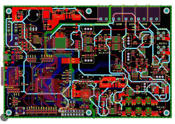
Step 1: Confirm Which Revision Will Be Used for the Prototype
One practical risk during the prototype stage is that different manufacturing documents may not belong to the same design revision.
After receiving the files, the manufacturer will typically confirm the Project / Part Number, PCB Revision, BOM Revision, Gerber Revision, Prototype Quantity, and Target Lead Time to ensure that the build uses one consistent and valid data set.
For example, the customer may upload Gerber files for Rev B while the BOM has already been updated to Rev C. If the two revisions include changes to component placement, circuitry, or board-level structure, proceeding with manufacturing creates a clear risk.
Similar issues may also occur between the Assembly Drawing, Pick-and-Place file, and BOM.
The prototype does not necessarily need to have reached a formally released production revision. What matters more is that both parties clearly agree on which set of files is the valid manufacturing data for this build.
If the wrong revision is used, the prototype may fail to provide the intended validation value, even if the subsequent PCB fabrication and SMT assembly fully comply with the manufacturing process.
Step 2: Review the Gerber Files and PCB Fabrication Requirements
Once the revision has been confirmed, the PCB manufacturing data enters engineering review.
This review mainly covers the Board Outline, Layer Data, NC Drill Data, Stackup, Copper Thickness, Finished Board Thickness, Surface Finish, Controlled Impedance, Via Structure, and any project-specific manufacturing tolerances and panelization requirements.
For a conventional prototype design, this review may be completed relatively quickly.
If the project involves HDI, Blind / Buried Vias, Rigid-Flex construction, Fine-Pitch BGA components, special materials, or clearly defined impedance, board thickness, and tolerance requirements, the engineering review is usually more detailed.
Gerber files primarily define the manufacturing patterns for each layer. They do not necessarily provide complete information about the material, finished board thickness, impedance targets, stackup, or other special fabrication requirements. These details usually need to be supplemented by a Fabrication Drawing, Stackup, or project specification.
If the engineer identifies manufacturability concerns, the manufacturer may provide DFM recommendations. However, if a recommendation affects traces, pads, structures, or other aspects of the design intent, it should be implemented only after customer approval rather than being treated as an automatic design change.
Step 3: The BOM Review Usually Takes Place in Parallel
While the PCB data is being reviewed, the Component Sourcing team will usually begin checking the BOM as well.
For a prototype PCBA, the BOM is more than a list of materials. A single unavailable critical component, an unclear MPN, or an unapproved alternative can directly affect whether the project can start on schedule.
The review typically verifies the Reference Designator, Manufacturer, Manufacturer Part Number, Quantity, Package, and DNP / DNI Status. It also checks component Availability, MOQ, Standard Package Quantity, Lead Time, and whether any parts are marked EOL or NRND.
If all critical components have clearly specified MPNs, the sourcing evaluation is much more straightforward.
By contrast, if the BOM only lists items such as “10k resistor,” “MCU,” or “connector” without a clear Manufacturer Part Number or sufficient selection criteria, the supplier may not be able to determine which brands, packages, ratings, or alternatives the customer will accept.
For medical electronics projects with strict design controls, it is especially important to clarify in advance whether critical components may be substituted. A supplier may recommend alternatives, but should not independently replace a critical component with a part that merely appears to have similar specifications simply to shorten the lead time or reduce cost.
Step 4: Cross-Check the BOM, Pick-and-Place File, and Assembly Drawing
The absence of obvious issues in the Gerber files and BOM does not necessarily mean that SMT assembly can begin immediately.
The assembly engineer must also confirm that the BOM, Pick-and-Place file, and Assembly Drawing correspond to one another.

For example, if the BOM includes:
R23 — 10 kΩ
the Pick-and-Place file should contain the corresponding placement data for R23, and the Assembly Drawing should confirm its actual assembly location.
Common issues in real projects include mismatched references between the BOM and Pick-and-Place file, conflicting DNP statuses, unclear component polarity information, or a mismatch between the footprint and the package specified by the MPN.
Rotation values also require particular caution.
Different CAD systems, output methods, and component libraries may use different conventions for rotation angles. Therefore, the Rotation Value in a Pick-and-Place file should not be used by itself to determine the final orientation of polarized components.
For directional components such as diodes, LEDs, ICs, and polarized capacitors, the orientation usually needs to be confirmed using the Assembly Drawing, component datasheet, package information, and the manufacturer’s own component library.
Issues involving design intent should be resolved before production rather than left for the operator to interpret on the production floor.
Step 5: The Engineering Team Will Ask the Customer for Clarification When Necessary
Many customers working on their first prototype discover that, after submitting the files, the supplier does not immediately reply, “Production has started.” Instead, the supplier sends several engineering questions first.
This is normal.
The earlier data conflicts are identified during the prototype stage, the lower the risk of PCB scrap, incorrect components, or rework later.
For example, the engineer may ask:
U12 specified in the BOM is currently unavailable. Can the approved alternative XXX be used?
The engineer may also identify an issue such as:
R37 is marked as DNP in the BOM, but it appears populated in the assembly drawing. Please confirm.
Or:
The fabrication drawing specifies a finished PCB thickness of 1.6 mm, while the provided stackup indicates 1.2 mm. Please confirm the build requirement.
Not every question will stop the entire project.
Issues that do not affect PCB fabrication or other material preparation may be handled in parallel, depending on the project. However, matters involving component substitutions, PCB specifications, polarity, critical structures, or test acceptance criteria usually require customer confirmation before the related work can be released.
Step 6: Once the Project Scope Is Clear, the Quote and Lead Time Become More Accurate
An initial RFQ can sometimes provide only a preliminary estimate based on the information available at that time.
As the PCB, BOM, assembly requirements, and testing scope become clearer, the supplier can more accurately calculate the costs for PCB Fabrication, Component Sourcing, SMT / THT Assembly, Inspection, Programming, Testing, and Fixture / NRE. The supplier can also make a more realistic assessment of the actual Lead Time.
For example, the initial RFQ may not define Functional Testing, but after engineering review, the customer may request FCT using a dedicated fixture. In that case, both the cost and lead time may need to be adjusted.
This is why providing only a PCB image, board dimensions, and a quantity such as “100 pcs” rarely results in a reliable complete PCBA quotation.
The clearer the project information is, the less likely it is that the supplier will need to re-quote later because of changes in scope.
Step 7: PCB Fabrication and Component Sourcing Move Forward Once Release Conditions Are Met
After the main technical issues have been closed and the quotation and commercial terms have been confirmed, the project can enter the appropriate manufacturing release stage.
Internal procedures vary by supplier. The actual release may also depend on the PO, payment terms, customer production authorization, or other commercial requirements.
At this stage, PCB fabrication and component sourcing do not necessarily need to proceed entirely in sequence.
If the PCB data is stable and there are no pending questions regarding critical materials, the two activities can often proceed in parallel, depending on the project conditions. This helps reduce the overall waiting time.
However, if a critical component alternative has not yet been approved, the stackup is still under discussion, or a new Gerber revision has just been received, the related work may need to remain on hold temporarily.
The goal in a prototype project is to control revision and material risks while moving forward in parallel with all activities that are already ready to proceed.
Step 8: Production Preparation Is Still Required Before SMT
From the customer’s perspective, once the PCBs are fabricated and all components have arrived, the next step may appear to be placing the boards on the SMT line.
In reality, there is still an important production preparation stage in between.
Depending on the project, the manufacturer may need to complete Stencil Preparation, SMT Program Setup, Feeder Preparation, Material Verification, First Article Preparation, Programming, Inspection Program Setup, and Test Fixture Preparation.
If the project includes moisture-sensitive components, the manufacturer must determine whether baking or other moisture-control measures are required based on the component MSL, packaging condition, and exposure time. Not every component requires baking.
For a new prototype, the placement program must be created and verified based on the Pick-and-Place data and the actual component packages. Inspection programs must also be prepared according to the actual PCB and component configuration.
If the project includes MCU Programming or Functional Testing, the Firmware, test program, and fixture should ideally be ready at this stage as well.
Therefore, there is usually a necessary engineering preparation period between “the PCBs and components have arrived” and “the finished PCBA can be completed immediately.”
Step 9: Prototype Assembly Officially Begins
Once the engineering and production preparations are complete, the prototype can officially enter assembly.
A typical SMT process includes Solder Paste Printing, Component Placement, and Reflow Soldering. If both sides of the PCB contain SMT components, the other side will be assembled according to the process plan. If the project includes THT or odd-form components, subsequent operations may include Selective Soldering or Manual Soldering.
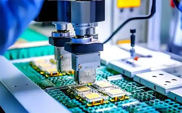
The exact process route depends on the board design and assembly requirements. Not every project follows exactly the same sequence.
For projects with fully confirmed documentation, SMT itself is often not the stage most likely to create a long delay during the prototype cycle.
More common sources of delay occur before production, such as document conflicts, shortages of critical components, pending alternative approvals, or missing Firmware, Fixtures, and test definitions.
Step 10: Inspection and Testing Are Performed According to the Project Requirements
The fact that the PCBA has completed reflow does not mean that the prototype can immediately be packed and shipped.
The agreed Inspection and Testing Scope must still be carried out.
| Item | Main Purpose |
|---|---|
| Visual Inspection | Check for obvious assembly abnormalities |
| AOI | Inspect visible component placement and soldering features |
| X-ray | Inspect hidden solder joints or internal structures that are suitable for X-ray evaluation |
| Programming | Load the customer-specified Firmware |
| Electrical Test | Perform board-level electrical checks according to the agreed test items |
| FCT | Verify functionality under defined test conditions |
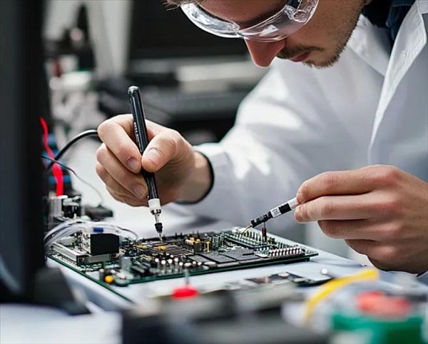
Not every medical prototype must undergo all of these inspections and tests.
X-ray, in particular, should be evaluated based on the component package and project requirements. Bottom-terminated packages such as BGA, LGA, and QFN may be more suitable for X-ray inspection of hidden connections. However, whether X-ray is required for first-article inspection, sampling, or 100% inspection should be determined based on design risk, customer requirements, and the established Inspection Plan.
ICT and FCT are also not automatically required for every medical PCBA.
Whether these tests are needed, and to what extent, should be determined according to the prototype’s validation objectives, the customer’s test specification, and the planned system-level validation approach.
The earlier the testing scope is defined, the less likely it is that the team will discover after production that a Fixture, Firmware, or Test Program is missing.
What Else Needs to Be Confirmed for a Medical PCB Prototype?
Medical PCBA prototypes do not use an entirely different set of basic PCB fabrication and assembly processes from other electronic products.
The main difference is how the project requirements are defined, controlled, and documented.
Traceability
Depending on the project requirements, it may be necessary to record the PCB Production Lot, Component Lot / Date Code, PCBA Production Batch, Serial Number, and related Material / Process Records.
The required level of traceability varies from one medical project to another.
If a later Pilot or Repeat Production stage is already expected to require more detailed Traceability Data, establishing the recording method during the prototype stage will make the transition smoother.
Inspection and Test Records
Some prototypes require only basic inspection results. Others may require records for X-ray, Programming, Functional Testing, or data linked to individual Serial Numbers.
These requirements affect the programs, fixtures, data collection, and production record methods, so they should not be defined only after the PCBA has been completed.
IPC / Workmanship Requirements
IPC-A-610 provides acceptance criteria for electronic assemblies, but the fact that a product is used in medical equipment does not automatically determine that a project must use a particular Class.
If the project follows IPC-A-610, J-STD-001, or the customer’s own Workmanship Specification, the applicable standard, Class, revision, and any additional customer requirements should be clearly stated in the project documentation or purchasing requirements.
Instead of simply telling the manufacturer:
“This is a medical PCB.”
it is more useful to specify which Workmanship, Inspection, Testing, Traceability, and Documentation Requirements apply to the project.
ISO 13485 Is Not the Same as Specific Manufacturing Requirements
ISO 13485 applies to quality management systems related to medical devices.
It can be part of a supplier quality-system evaluation, but it does not by itself specify which PCB Stackup the prototype must use, which IPC Class applies, whether ICT is mandatory, or which components must undergo 100% X-ray inspection.
These project-level requirements still need to be defined by the customer and manufacturer based on the product, design, risks, and purchasing specifications.
Change Control
A prototype is itself part of the design verification and issue-discovery process.
If the PCB Design, Component, Approved Alternative, Assembly Method, Programming, or Test Condition needs to change during the project, the change should be reviewed and approved according to the agreed Engineering Change / Approval process.
Changes that affect functionality, critical materials, or an already approved customer design should not be decided independently by the manufacturer simply to meet the delivery schedule.
Which Issues Are Most Likely to Delay a Prototype?
Prototype Lead Time does not depend only on SMT production speed.
In actual projects, waiting time often comes from three types of issues.
The first is that the documents are not fully aligned.
If the Gerber files, BOM, Pick-and-Place file, and Assembly Drawing belong to different revisions, or if the DNP, Polarity, and Placement Information conflict, repeated engineering clarification may be required.
The second is that critical materials are not ready.
An inaccurate MPN in the BOM, a shortage of a critical component, or an Approved Alternative that has not been confirmed in advance can directly affect the sourcing schedule. In some projects, a single long-lead-time IC can become the critical path for the entire prototype.
The third is that the testing requirements are provided too late.
If the Firmware, Programming, Fixture, or Test Specification is not provided until late in the production process, the PCBA may already be assembled but still unable to complete testing and delivery on schedule.
Shortening the prototype cycle often depends first on having clear documentation, materials, and testing inputs—not simply on choosing a supplier that claims to have very fast SMT production.
What Happens After the Prototype Is Completed?
Completing the first batch of PCBAs means that the project has obtained physical units for engineering evaluation and subsequent validation. It does not automatically mean that the project is ready for mass production.
A typical path may be:
Prototype Build → Engineering Evaluation → Issues / Changes → Updated Revision → Repeat Prototype or Pilot Build → Production Readiness
After receiving the prototypes, the customer may continue with board-level testing, system integration, Firmware debugging, and product-level validation.
If issues are discovered, the PCB, BOM, Firmware, or test plan may all be revised.
An early prototype is mainly intended to answer the question:
“Once this design is built according to the current revision, can it support the intended engineering validation?”
As the project approaches a Pilot Build, the focus gradually shifts toward:
“Can the PCB, BOM, sourcing channels, assembly process, Inspection, and Testing continue to be produced in a controlled and repeatable manner?”
Therefore, successfully completing one prototype build can provide important evidence for the next stage, but it does not by itself prove that the project is ready for mass production.
What Information Should Be Prepared Before Sending a Prototype RFQ?
To help the manufacturer complete the engineering review and quotation more quickly, prepare the following information whenever possible:
- Gerber Files + NC Drill Files
- BOM with Manufacturer Part Numbers
- Pick-and-Place / Centroid File
- Assembly Drawing
- PCB Fabrication Specification / Stackup, if applicable
- Prototype Quantity
- Programming Files / Requirements
- Inspection Requirements
- Testing Requirements
- Traceability Requirements
- Target Lead Time
If the project requires Functional Testing or debugging support, the relevant Test Specification, Firmware, and necessary interface information should also be prepared as early as possible.
Of course, not every document must be fully frozen for mass production before you contact a manufacturer for the first time.
For projects that are still in the NPI or prototype stage, you can submit the current Gerber files, BOM, and available engineering documents first. This allows the manufacturing team to identify which fabrication, sourcing, or testing inputs are still missing.
Frequently Asked Questions
Can I request a PCB assembly quotation with only the Gerber files and BOM?
Usually, they are sufficient for an initial engineering review and cost estimate.
However, to accurately evaluate the complete Assembly Scope, the manufacturer will typically also need the Pick-and-Place / Centroid File, Assembly Drawing, and any applicable Programming, Inspection, and Testing Requirements.
The more complete the documentation, the fewer assumptions the supplier needs to make in the quotation.
Will the PCB manufacturer start production immediately after receiving the files?
Usually not.
The manufacturer first needs to confirm the valid file revision for the build and review the PCB Fabrication, BOM, Component Availability, and Assembly Data.
The timing of the formal release also depends on whether the engineering issues have been closed and on the supplier’s own commercial and production authorization procedures.
What should I do if a component in the BOM is unavailable?
The manufacturer can evaluate available inventory, procurement Lead Time, or customer-approved alternatives.
If a new Alternative Component needs to be introduced, the relevant technical review should be completed first, especially for critical components that may affect functionality, reliability, regulatory documentation, or an already approved design.
Will a DFM Review modify my PCB design?
The main purpose of a DFM Review is to identify issues that may affect manufacturing and provide manufacturing-related recommendations.
If a recommendation involves changes to traces, pads, components, or critical structures, it should be implemented only after customer approval.
A DFM review does not authorize the supplier to modify the customer’s design without approval.
Is FCT always required for a medical PCB prototype?
No.
Whether FCT is required, which functions should be tested, and what type of Fixture should be used should be determined according to the prototype’s validation objectives and the customer-defined Test Specification.
The testing scope required for a basic assembly check is not the same as that required for complete board-level functional validation.
Is IPC Class 3 always required for a medical PCB prototype?
No.
The medical application itself does not automatically determine the applicable IPC Class.
If the project requires a specific IPC-A-610 / J-STD-001 Class or customer-defined Workmanship Criteria, it should be clearly stated in the project specification and purchasing documents.
Can the project go directly into mass production after a successful prototype?
Not necessarily.
The first prototype can help validate the current design and manufacturing inputs. Before entering repeat production, the project should confirm, as appropriate, that the PCB/BOM Revision, Component Sourcing, Assembly Process, Inspection / Testing, Fixture, Traceability, and Manufacturing Documentation are stable.
If the design still requires changes, the next step may be another prototype or a Pilot Build.
From Gerber Files and BOM to the First Medical PCBA
Submitting the Gerber files and BOM is only the beginning of prototype manufacturing.
Before the first PCBA actually enters SMT, the manufacturer typically needs to complete revision confirmation, PCB engineering review, BOM Review, component availability assessment, Assembly Data cross-checking, engineering issue closure, and the necessary production and testing preparations.
Most of this work does not take place on the SMT production line, but it directly affects whether the prototype is built with the correct PCB, the correct materials, and the manufacturing requirements agreed upon by both parties.
If your project is ready with the Gerber files, BOM, Pick-and-Place file, Assembly Drawing, Prototype Quantity, and testing requirements, you can submit the complete package to a Medical PCB Assembly Manufacturer for engineering review.
For projects that are still in the NPI stage, you can also begin with the available design data and allow the manufacturing team to identify which PCB fabrication, component sourcing, and testing issues still need to be confirmed.
Send Your Gerber & BOM for a Medical PCB Prototype Review