
Choosing a medical PCB assembly partner for a prototype involves more than checking a certificate and requesting a quick-turn quotation. The practical question is whether the supplier can help move the board from a flexible engineering build to a controlled and repeatable production process.
Prototype testing often relies on bench instruments, manual probing, adjustable procedures, and board-by-board debugging. Those methods are useful because engineers are still learning how the hardware behaves. Production testing has a different purpose. It needs controlled firmware, repeatable fixtures or interfaces, documented procedures, defined limits, and records that identify what was tested.
A prototype that powers on and passes manual checks is an important milestone, but it does not prove that hundreds of units can be assembled and tested in the same way. A useful partner should identify this transition early and explain how DFM, test planning, traceability, and change control will develop as the design matures.
Prototype Success Does Not Prove Production Readiness
Prototype and production builds answer different questions. A prototype asks whether the current design can support engineering evaluation. A production process asks whether the approved configuration can be reproduced without depending on one engineer’s judgment.
| Area | Prototype build | Production build |
|---|---|---|
| Primary purpose | Find design, assembly, and testability problems | Reproduce the approved build consistently |
| Test method | Bench instruments, manual probing, adjustable procedures | Controlled fixtures or interfaces and documented procedures |
| Pass criteria | May include engineering interpretation | Defined limits with clear pass and fail results |
| Configuration | Design and firmware may still change | Released PCB, BOM, firmware, fixture, and test revisions |
| Records | Debug notes and engineering observations | Lot or unit results linked to the approved configuration |
Problems arise when a manual prototype procedure is treated as if it were already a production test. The engineer may know where to probe, which reading is acceptable, and how to interpret a marginal waveform, but that knowledge is not yet a controlled manufacturing process.
Define the Production Test Before Scale Up
The transition should begin while the prototype is still being evaluated. The OEM and manufacturer should identify which board functions require verification, which limits determine pass or fail, what test access is available, and which firmware and test-program revisions will control the result.
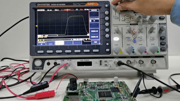
Manual oscilloscope and multimeter measurements can reveal behavior that a simple production fixture might miss. The production-test design should convert the relevant engineering observations into repeatable checks rather than discard them when manual probing becomes impractical.
Control Fixtures Firmware and Limits
If the board requires programming or functional testing, control the fixture configuration, programming file, firmware revision, test-program revision, measurement limits, and record format. A passing result has little investigative value if the team cannot identify which software, fixture, or limits produced it.
Design for test should also be reviewed before the layout is frozen. Test points, programming pads, connector access, fixture clearance, grounding, and measurement bandwidth can determine whether the intended production test is practical. The PCB assembly DFM checklist provides a broader pre-build review, while test access should be assessed against the functions that the production process must verify.
Separate Inspection From Functional Verification
SPI, AOI, and X-ray inspection evaluate different manufacturing features. They do not prove that the assembled board performs every required function. Electrical and functional tests can verify selected circuit conditions and board behavior, but their coverage depends on the design, fixture, test program, and limits.
The inspection and test plan should therefore state what each method covers and what remains outside its scope. See SugaMed’s overview of PCB assembly inspection and testing for the roles of SPI, AOI, X-ray, ICT, flying-probe testing, and functional testing.
What ISO 13485 and IPC A 610 Establish
ISO 13485 specifies quality-management-system requirements for organizations involved in medical devices and related services. IPC-A-610 provides post-assembly acceptance criteria for electronic assemblies. They address different subjects, and neither one replaces the project’s approved manufacturing data, inspection plan, test specification, or complete-device verification.
When an OEM evaluates ISO 13485 certification, it should verify the certified site and scope rather than relying only on a logo or company name. When an IPC class is required, the applicable standard revision, class, and any customer-specific criteria should be identified in the purchasing and manufacturing documentation. A medical application does not automatically make every assembly a Class 3 product.
Start Traceability With the First Build
Prototype records can become important during design review, qualification, failure investigation, or later production transfer. Depending on project requirements, the first build may need to record the PCB revision, BOM revision, component lots or date codes, approved substitutions, firmware revision, inspection results, test results, rework, and deviations.
Waiting until volume production to define these records creates gaps that may be impossible to reconstruct. The required traceability level should match the decisions the records need to support. Some projects need lot-level history, while others require a serial number and test record for each PCBA.
Keep Regulatory Ownership Clear
A PCBA manufacturer can provide controlled manufacturing and test records that support the customer’s technical documentation. The manufacturer does not automatically own the regulatory submission or complete-device compliance work.
For example, IEC 80601-2-30 addresses the basic safety and essential performance of automated non-invasive sphygmomanometers, IEC 60601-1 covers general requirements for medical electrical equipment, and ISO 80601-2-61 applies to pulse oximeter equipment. Manufacturing records may support the OEM’s work, but they do not by themselves demonstrate that the complete device meets those standards.
Risk Specific DFM for Medical Prototype PCB Assembly
A useful DFM review should connect manufacturing and test risks to the actual design. A generic checklist may identify common footprint or spacing issues, but it may miss the circuit areas most likely to affect measurement quality or production testing.
Blood Pressure Monitor PCBA
For a blood pressure monitor PCBA, the review may focus on the pressure-sensor signal chain, analog and digital return paths, pump and valve driver switching noise, instrumentation-amplifier routing, ADC reference stability, and access for realistic inflation and deflation testing.
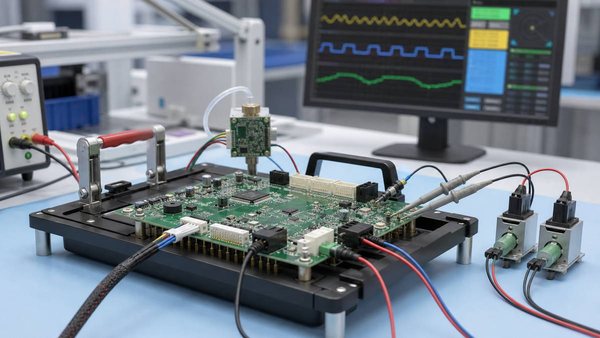
A power-on test can confirm that the controller starts, but it may not reveal interference from the pump driver or instability in the sensor path. The functional test should exercise the board under defined pressure conditions and verify the signals and outputs that matter to the OEM’s design.
Pulse Oximeter PCBA
For a pulse oximeter PCBA, the relevant risks differ. The review may include LED-drive isolation, photodiode receive routing, analog and digital return currents, decoupling placement, optical-interface connections, and the way the test setup supplies a controlled input to the signal chain.
A marginal layout may pass continuity and power-on checks but still produce unstable or noisy measurements when the device processes an actual physiological signal. These risks should be considered before the first build so the prototype can test more than basic assembly continuity.
Questions to Ask a Prototype Assembly Partner
The following questions reveal more than a certificate list or a standard quick-turn quotation.
| Question | Evidence to look for |
|---|---|
| Does the quality-system scope cover the facility and work? | The certificate identifies the correct site and a scope relevant to the outsourced activity |
| Is the DFM review specific to the design? | Feedback refers to actual nets, packages, signal paths, process limits, and test access |
| How will testing change after the prototype? | A plan for fixtures, firmware, procedures, limits, records, and production ownership |
| How are BOM and lifecycle risks handled? | Approved manufacturer part numbers, controlled alternates, availability checks, and early risk reporting |
| How are revisions and deviations controlled? | Records connect each build to its PCB, BOM, firmware, test, rework, and approval status |
How SugaMed Supports the Transfer to Production
SugaMed focuses on PCB assembly for patient-monitoring and related medical electronics, including blood pressure monitors, pulse oximeters, clinical monitoring equipment, and wearable monitoring devices. Manufacturing can be controlled under ISO 13485 quality processes and to the IPC acceptance class specified for the project.
The engineering review considers both general manufacturability and application-specific risks. For blood pressure monitor boards, this may include the pump and valve drivers and the pressure-sensor signal chain. For pulse oximeter boards, it may include LED drive, photodiode routing, and analog signal integrity.
After complete design files and a BOM are submitted, DFM feedback is typically targeted within 24 hours. Prototype builds commonly require 7 to 10 working days after the manufacturing data, materials, and test requirements are ready. Production timing often falls in a 4 to 6 week range, but actual schedules depend on BOM complexity, component availability, tooling, testing, and the required records.
Depending on the project, support may extend beyond PCBA to programming, functional testing, cable and enclosure integration, labeling, packaging, and related manufacturing documentation. The scope should be agreed before the build so the quotation and schedule reflect the work required.
Information to Prepare Before Engineering Review
A more complete input package allows the manufacturer to identify conflicts and testability risks earlier. Prepare the following information when available:
- Gerber files and NC drill data
- BOM with manufacturer part numbers and approved alternatives
- Pick-and-place data and assembly drawings
- PCB fabrication specification and stackup when applicable
- Prototype quantity and target schedule
- Firmware and programming requirements
- Inspection and functional-test requirements
- Traceability and manufacturing-record requirements
If some information is still under development, identify the current revision and the decisions that remain open. The medical PCB prototyping process explains what usually happens after the Gerber files and BOM are submitted.
Use the First Review to Evaluate the Partner
The quality of the first engineering review often provides better evidence than the speed of the first quotation. A useful review identifies the specific manufacturing, sourcing, test, and configuration risks that could prevent a successful prototype from becoming a repeatable production build.
Send SugaMed your Gerber files, BOM, assembly drawing, prototype quantity, and test requirements for an initial review. The team can evaluate manufacturability, component availability, inspection coverage, test planning, and the controls needed for later production. Contact SugaMed to discuss your medical prototype PCBA project.