
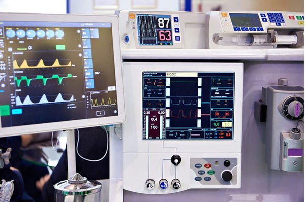
Medical PCB assembly uses many of the same manufacturing technologies as other high-reliability electronics. Solder paste printing, surface-mount placement, reflow soldering, AOI, X-ray inspection, programming, and functional testing are not unique to medical products.
What distinguishes a medical electronics project is the level of control applied to revisions, materials, processes, inspection, testing, traceability, and changes. A board that powers on has passed an important engineering milestone, but it is not automatically ready for repeat production.
Once a project moves through NPI and a pilot build, the manufacturer must be able to reproduce the approved build under controlled conditions. The OEM should be able to identify which materials were used, which inspections and tests were performed, which software and test-program revisions applied, and how any deviation or change was approved.
What Medical PCB Assembly Includes
Medical PCB assembly is the process of mounting electronic components on printed circuit boards used in medical, diagnostic, therapeutic, and related electronic equipment, followed by the required soldering, inspection, programming, and testing.
Depending on the project scope, the service may include component sourcing, SMT and through-hole assembly, firmware programming, AOI and X-ray inspection, ICT, flying-probe testing, functional testing, and production records.
PCB manufacturing and PCB assembly describe different stages. PCB manufacturing produces the bare board, including the conductors, stack-up, vias, solder mask, and surface finish. Assembly begins with component installation and continues through soldering, inspection, programming, and test.
The word medical does not prescribe one special soldering method. The applicable controls come from the device, the OEM’s approved design, the project quality requirements, and the evidence that must be retained.
Define the Approved Build Before Production
Many problems that appear on the SMT line begin earlier, when the manufacturing package has not been aligned and released as one controlled configuration.
Before production, confirm the PCB revision, BOM revision, approved manufacturer part numbers, permitted alternates, pick-and-place data, assembly drawing, and project-specific process and acceptance requirements. A PCBA built with the wrong BOM revision is not the approved product even if every solder joint is acceptable. An unapproved component substitution does not become acceptable simply because AOI and functional testing pass.
Programmable devices add another layer of configuration control. If the assembly contains an MCU, wireless module, FPGA, flash memory, or another programmable device, control the firmware revision, programming file, programming method, programming verification, and test-program revision. A pass or fail result must identify the test program, fixture configuration, and limits that produced it.
Complete DFM and DFT review before release whenever possible. DFM evaluates whether the design and manufacturing data support a stable build. DFT evaluates whether programming, electrical testing, and functional verification have adequate access and coverage. The review should consider BGA and QFN inspection, test-point access, programming pads, fixture access to connectors, and whether shielding or mechanical parts will obstruct the test interface. Our PCB assembly DFM checklist provides a practical pre-RFQ review.
Control Each Assembly Step
A basic process diagram might show solder paste printing, placement, reflow, AOI, X-ray inspection, and testing. OEMs need a more useful view: what each step controls and what evidence it can leave behind.
| Stage | Main control | Typical record |
|---|---|---|
| Incoming materials | PCB and component identity, revision, source, and status | Incoming and lot records |
| Solder paste printing | Stencil, paste, and deposited volume or position | SPI results |
| Component placement | Part identity, polarity, orientation, feeder, and program | First article and AOI records |
| Reflow soldering | Soldering process and product-specific thermal profile | Profile and inspection records |
| Hidden solder joints | BGA, QFN, or LGA solder condition | X-ray results |
| Programming | Approved software or firmware revision | Programming record |
| Electrical and functional test | Defined circuit conditions and board-level functions | ICT, flying-probe, or FCT results |
| Release | Correct approved production configuration | Lot or serial-number record |
Incoming Material Printing and Placement Controls
Production control starts before solder paste printing. Confirm that the PCB matches the released revision, that components match the approved BOM, and that purchasing used permitted supply channels. Depending on the project, records may include the PCB lot, component lot, manufacturer date code, moisture-sensitivity status, and packaging condition. These records should answer a practical question during an investigation: which materials were used in this build?
SPI moves the detection of printing problems ahead of placement and reflow. It can identify paste offset, insufficient deposits, or excessive deposits, but it evaluates the printing step only. It does not prove that every final solder joint is acceptable or that the completed board functions correctly.
Placement control covers more than machine accuracy. It also covers component identity, polarity, orientation, feeder setup, and the placement program. First-article verification is particularly valuable for new products and builds affected by a revision change.
Reflow and Through Hole Assembly Controls
Reflow settings should match the solder paste, components, PCB construction, board thickness, and thermal mass. A profile developed for one assembly should not be copied mechanically to every product.
Through-hole assembly is not a standard step for every medical PCBA. Some projects use connectors, transformers, relays, switches, or mechanically loaded components that require through-hole attachment. Others use almost entirely surface-mount components. The component and mechanical requirements should determine the process.
Define Inspection and Test Coverage
A long equipment list does not demonstrate complete coverage. The inspection plan should state what each method can detect, what remains outside its view, and how the methods work together. See our overview of PCB assembly inspection and testing for related capabilities.
SPI and AOI Find Visible Process Problems Earlier
SPI evaluates solder paste deposits before reflow. AOI can check component presence, polarity, orientation, placement, and some visible solder conditions. AOI is limited to features that the optical system can see. It cannot directly inspect BGA solder joints hidden under the package in the same way that it inspects exposed leads.
X Ray Evaluates Hidden Solder Joints
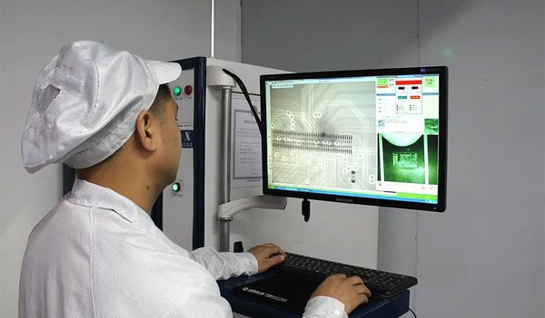
X-ray inspection is especially useful for BGA, QFN, LGA, and other packages with hidden or partly hidden solder joints. Depending on the package and inspection method, it can help identify bridging, possible open conditions, abnormal solder distribution, voiding, and other internal solder features.
X-ray remains a structural inspection method. It does not replace board-level functional verification. For SugaMed prototype SMT assemblies, 100 percent post-reflow AOI and 100 percent X-ray inspection of BGA solder joints assign different risks to the inspection methods best suited to them.
ICT Flying Probe and Functional Test Need Defined Coverage
ICT and flying-probe testing can check opens, shorts, resistance, and selected component-level electrical conditions. Coverage depends heavily on the DFT design. If critical nodes have no test points or become inaccessible after assembly, the availability of ICT equipment does not mean that every important circuit can be verified.
Functional testing is closer to the actual board-level behavior. It may verify power rails, communication interfaces, sensor inputs, outputs, programming, and other functions defined by the OEM.
A board that passes FCT has passed the functions and limits implemented in the approved test program. The result does not establish that every use condition has been evaluated, and it does not by itself prove compliance of the complete medical device. Treat SPI, AOI, X-ray, ICT, and FCT as an inspection and test coverage strategy rather than a list of equipment.
Define Traceability in Usable Terms
The phrase full traceability is incomplete unless both parties know which records it includes. A useful traceability plan usually covers three areas.
- Design and configuration may link the PCB revision, BOM revision, approved engineering changes, firmware revision, programming file, and test-program revision. It answers which approved version the board represents.
- Materials may include the PCB lot, component lot, manufacturer date code, supplier, solder-paste batch, or coating batch. The OEM and manufacturer should define the required granularity before production.
- Production inspection and test may include the production lot, work order, AOI result, X-ray record, ICT or FCT result, rework record, and deviation record.
SugaMed can establish lot-, component-, and serial-number-level traceability according to project requirements. The practical value appears when a component lot, PCB revision, or test program becomes suspect and the records help identify which PCBAs may be affected.
Some projects need lot-level traceability; others need a serial number and test history for each board. Define the quality decisions and investigations that the records must support, then select the traceability level.
Move From Working Prototypes to Repeatable Production
A prototype answers whether the design can work. Repeat production must answer whether the approved build can be manufactured consistently under normal production conditions. These are different questions.
Convert Engineering Workarounds Into Standard Processes
During a small prototype run, an engineer may make manual adjustments, perform temporary repairs, use selective testing, work with a temporary fixture, or spend more time troubleshooting. Those actions may be appropriate during development. The risk arises when prototype-only practices continue into normal production without being defined and controlled.
If the production team cannot identify the approved assembly program, fixture, firmware, alternates, inspection criteria, and work instruction, a successful prototype build does not demonstrate a mature process.
NPI and the pilot build should convert decisions that depend on an individual engineer into standard settings, test methods, and work instructions. Review whether process settings are stable, whether AOI or X-ray repeatedly finds the same defects, whether the test fixture supports repeated use, whether FCT coverage is adequate, whether traceability records are reliable, and whether operators can follow the work instruction without continuous engineering intervention.
Monitor Process Stability Beyond Final Pass Rate
Final pass rate can hide an unstable process. Two lots may both reach 100 percent final pass, but a lot that required extensive touch-up, rework, troubleshooting, and retesting is not in the same manufacturing state as a lot with a high first-pass yield.
During production transfer, monitor first-pass yield, recurring defects, rework frequency, and repeated AOI, X-ray, or FCT findings. These results help distinguish a stable process from one that depends on correction and retesting to achieve the final result.
Establish a Production Baseline and Control Changes
Before repeat production, the OEM and manufacturer should identify the approved build baseline. It may include the PCB revision, BOM revision, approved materials, assembly program, firmware, inspection criteria, test method, fixture configuration, work instruction, and traceability requirements.
A component substitution, PCB revision, program change, fixture modification, firmware update, or test-limit change should then be evaluated against that approved baseline. Change control is part of PCB assembly quality control.
Define Project Specific Medical Assembly Requirements
The word medical does not define every manufacturing requirement. The OEM should identify the requirements that apply to the device and the outsourced activity.
- IPC product class should be specified in the approved documentation. Some medical electronics projects use Class 3, but the product label alone does not make Class 3 mandatory. IPC describes J-STD-001 as a soldering process and materials standard and IPC-A-610 as a post-assembly acceptance standard; the parties should agree on the applicable revision, class, and customer requirements.
- Cleanroom or another controlled environment should follow the product’s contamination sensitivity, downstream process, and OEM requirements. Cleanroom capability is not a universal prerequisite for medical PCBA.
- Sterilization compatibility matters only when the PCBA, conformal coating, connector, or another relevant material will be exposed to ethylene oxide, radiation, steam, or another sterilization process. Evaluate the actual exposure rather than applying a general sterilization requirement to every internal electronic assembly.
- Quality and regulatory frameworks address different subjects. ISO 13485 specifies quality-management-system requirements for medical-device organizations and relevant suppliers. The FDA Quality Management System Regulation, effective February 2, 2026, incorporates ISO 13485:2016 by reference into 21 CFR Part 820. ISO 14971 addresses medical-device risk management. These frameworks do not replace PCB-assembly acceptance criteria or complete-device verification.
Passing AOI or meeting an IPC acceptance requirement does not, by itself, demonstrate that a complete medical device has finished regulatory, safety, and risk verification.
What OEMs Should Check Before Scale Up
A full supplier qualification requires its own review, but three questions are especially important before repeat production.
- Does the quality-system scope cover the outsourced work? If ISO 13485 support is required, verify the certificate site and scope and confirm that the actual PCB or PCBA activity is included. A certificate logo alone is not enough.
- Does the inspection and test strategy match the board? Identify which packages are inspected, when inspection occurs, what FCT verifies, who defines pass and fail, and which records are retained.
- Did the pilot build demonstrate repeatability? The final question is not only whether the supplier can build one board. It is whether the supplier can reproduce the approved build with a stable process, defined inspection and test coverage, controlled changes, and usable manufacturing records.
Medical PCB Assembly Preproduction Checklist
Before repeat production, confirm that:
- PCB and BOM revisions are approved and aligned
- Approved component sources and alternates are defined
- DFM and DFT issues are closed or formally accepted
- Firmware, programming files, and test programs are controlled
- SPI, AOI, X-ray, and other inspection coverage is defined
- The functional-test fixture, limits, and record requirements are approved
- Lot-level or unit-level traceability is defined
- NPI and pilot-build repeatability issues are closed
- Engineering-change, substitution, deviation, and rework rules are documented
- The production baseline is formally released
Reliable medical PCB assembly does not come from adding the maximum number of inspection machines to an SMT line. It comes from repeatedly building, inspecting, testing, and identifying the same approved product under a controlled manufacturing configuration.
If your project is at the prototype, NPI, pilot, or repeat-production stage, send SugaMed your Gerber files, BOM, assembly drawing, and test requirements. We can review assembly risks, inspection coverage, BGA and QFN X-ray needs, functional testing, traceability, and the scope of ISO 13485-controlled manufacturing before the build begins. Contact SugaMed for an initial project review.