
Completing SMT, through-hole (THT), or other assembly processes does not mean that a blood pressure monitor PCB is ready to go straight into final device assembly.
After assembly, inspection and testing need to answer several practical questions. Are the components placed correctly? Are there visible soldering defects? Can the critical circuits power up normally? Can the firmware be programmed correctly? Do board-level interfaces associated with the pressure sensor, pump, and valve operate as the design requires?
These activities are part of quality control and board-level testing at the PCB assembly stage. They can help the manufacturing team find assembly and functional problems before the board enters device integration, but they cannot replace final calibration, measurement-accuracy verification, or regulatory validation of the finished blood pressure monitor.
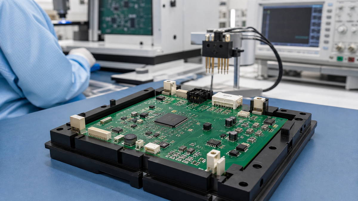
This article follows the manufacturing flow of a blood pressure monitor PCBA and explains the inspection and test methods commonly used after assembly, along with the problem each method is intended to address. For a broader overview of available methods, see PCB Assembly Testing Methods and Their Applications.
Table of contents
- What Does Blood Pressure Monitor PCB Assembly Testing Cover?
- AOI and X-Ray Inspection After Assembly
- Power and Basic Electrical Checks
- Firmware Programming and MCU Checks
- Pressure-Sensor Interface Testing
- Pump and Valve Driver Testing
- Communication and Other Interface Checks
- When Is a Test Fixture Needed?
- PCBA Testing Is Not Blood Pressure Monitor Calibration
- Prototype vs Production Testing
- Test Records and Traceability
- Blood Pressure Monitor PCB Assembly Testing Checklist
- From PCB Assembly Testing to the Finished Blood Pressure Monitor
What Does Blood Pressure Monitor PCB Assembly Testing Cover?
A blood pressure monitor control board may integrate a pressure-sensor interface, MCU, pump and valve drivers, power circuitry, display interfaces, and communication circuitry.
The test plan will not be identical for every project. Its actual scope usually depends on the PCB design, component packages, firmware, test procedure, test fixture, and customer-defined acceptance criteria.
Common inspection and test activities include the following:
| Inspection / test | Primary purpose | Typical stage |
|---|---|---|
| SPI | Solder-paste volume, area, height, and positional offset | After SMT printing |
| AOI | Missing or shifted components, polarity, and visible solder-joint defects | After reflow |
| X-ray | Hidden solder joints under BGA, LGA, QFN, or similar packages, where applicable | After assembly |
| Electrical checks | Power rails, shorts or opens, and selected critical electrical conditions | After assembly |
| Firmware programming | MCU firmware loading and basic start-up status | Board-level testing |
| Functional testing | Board-level interfaces and customer-defined functional responses | Board-level testing |
Not every blood pressure monitor PCB needs every test in this table. If the design has no package with hidden solder joints that warrants X-ray inspection, the test should not be added mechanically simply because the product is a medical electronic device. Likewise, a straightforward controller and a design with wireless communication, multiple sensor interfaces, or additional control functions will require different test coverage.
Where SPI is included in the process, its role and limitations are explained in Solder Paste Inspection (SPI) in PCB Assembly.
AOI and X-Ray Inspection After Assembly
The first layer of quality control after PCB assembly is usually the detection of manufacturing defects.
At this stage, the goal is not to determine whether the blood pressure monitor will produce accurate readings. The immediate goal is to identify assembly problems that production inspection can detect.
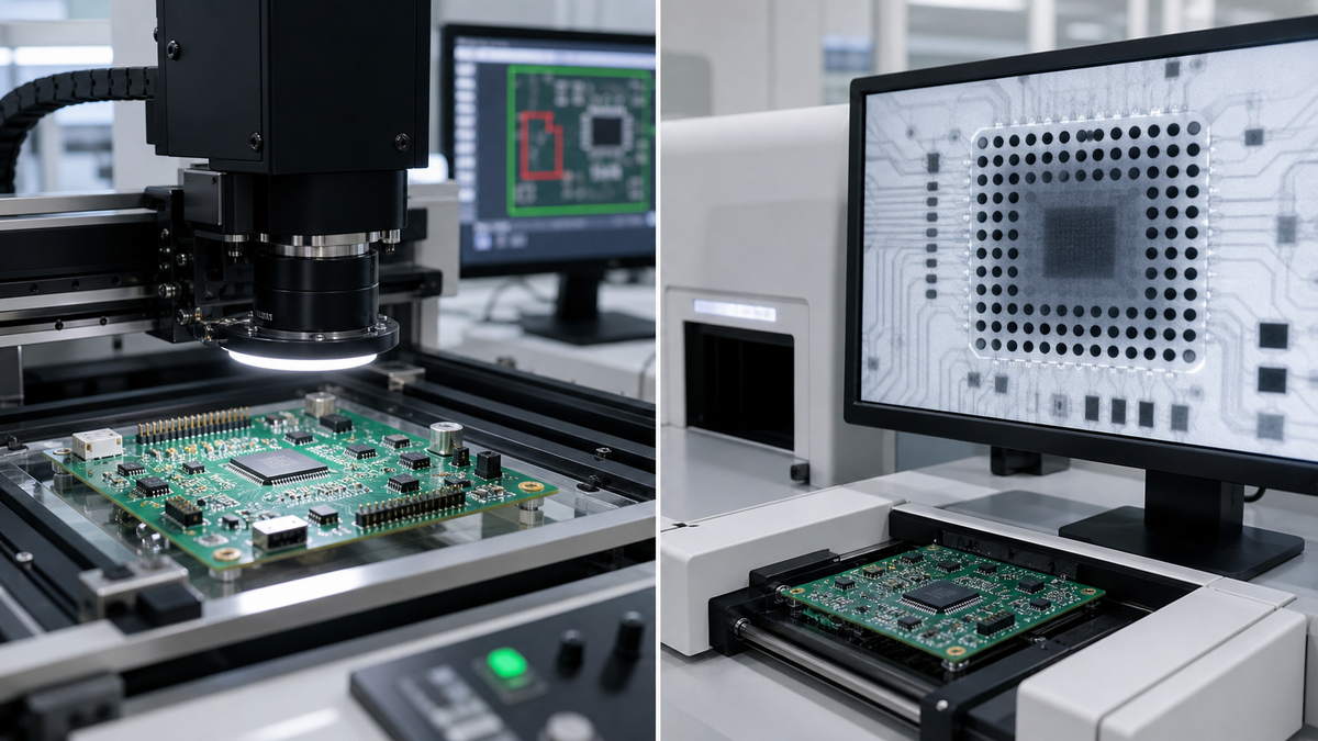
AOI: Visible Assembly Defects
Automated optical inspection (AOI) is mainly used to examine components and soldering conditions that remain visible from the board surface after reflow.
Depending on the equipment and inspection program, common checks include:
- missing components;
- component offset;
- polarity or orientation;
- certain visible solder defects.
For a blood pressure monitor PCB, AOI plays much the same role as it does for other electronic products: it finds obvious placement and soldering abnormalities early, before affected boards proceed to programming and functional testing.
AOI, however, depends primarily on optically visible information. It cannot provide a complete assessment of solder joints hidden beneath a component package.
When Is X-Ray Needed?
If the design uses BGA, LGA, QFN, or another package with hidden solder joints, the need for X-ray inspection should be decided according to the package structure, assembly risk, and project-specific inspection requirements.
X-ray can help reveal solder regions that optical equipment cannot see directly, including solder balls, bottom-side pads, and some voiding conditions. This is one of the reasons inspection planning matters in BGA assembly.
The decision to use X-ray should not be based on the product name “blood pressure monitor.” A more useful decision path is:
Component package + assembly risk + project requirement -> inspection method
This prevents an inspection method intended for specific package and risk conditions from being presented as a fixed requirement for every medical PCB.
Power and Basic Electrical Checks
Passing AOI does not prove that the board is electrically sound.
Before firmware programming and subsequent functional testing, the board normally needs to meet reasonable power-up conditions. Based on the customer-supplied test procedure and design data, board-level checks may cover the main power input, critical power rails, abnormal current draw, and obvious shorts or supply faults.
If the basic power system is already abnormal, attempting to start the MCU, pressure-sensor interface, or pump and valve drivers provides little test value and may increase the risk of component damage.
Universal voltage, current, or pass/fail limits are not appropriate for all blood pressure monitor PCBs. The applicable limits should come from approved design documents and test specifications for the project.
Firmware Programming and MCU Checks
Automatic blood pressure monitors normally rely on an MCU for data processing, pneumatic control, display management, communication, and other functions.
At the PCB assembly stage, firmware programming is often an important step before board-level functional verification. Depending on project requirements, the manufacturing process may include firmware loading followed by checks that the MCU starts normally, reaches the expected state, and responds through selected basic communication interfaces.
Medical electronics projects also require careful version alignment. The PCB revision, firmware version, and test-program version should match the current production build.
If the firmware has changed while the production line still uses an older test program, a board without any assembly defect may produce a misleading test result. Board-level testing is therefore not only an electrical operation; it also depends on controlled production files and version management.
Pressure-Sensor Interface Testing
The pressure sensor is a critical interface in a blood pressure measurement system. At the PCB assembly stage, however, the manufacturer is primarily verifying that the sensor interface and associated circuitry operate as designed—not validating the final accuracy of the blood pressure measurement.
The achievable test coverage depends on the sensor type and the customer-defined test method.
If the pressure sensor is already installed on the PCB, the test may confirm its supply, communication, or output response against the design requirements. For an analog-output sensor, suitable test conditions may also allow the team to observe whether a controlled input change produces the expected signal or ADC response. With a digital sensor, the test may focus more on interface communication, device response, or status readback.
The distinction must remain clear:
A functioning pressure-sensor interface does not mean that the finished device’s blood pressure measurement accuracy has been verified.
The final result also depends on the pneumatic path, cuff, sensor calibration, firmware algorithm, mechanical assembly, and finished-device calibration. The related signal chain and control relationships are explained in Blood Pressure Monitor Circuit Diagram: How the Sensor, Pump and Valve Work Together.
PCB assembly testing confirms the portion of the system that belongs to the board-level electronic hardware.
Pump and Valve Driver Testing
Automatic blood pressure monitors generally use a pump and valve to inflate and deflate the cuff. At the PCB assembly stage, the appropriate test targets are the pump and valve control circuits and their driver outputs—not the performance of the complete pneumatic system.
Using the customer-supplied test fixture, load conditions, and test procedure, the test can determine whether the MCU control signal reaches the driver circuit and whether the resulting output is in the expected state.
Checks may cover pump enable, valve control, and the corresponding driver outputs. Whether a real pump or valve is connected depends on the fixture design and project requirements. Some projects connect the actual load during board-level testing; others use an electrical dummy load to confirm that the control and driver circuits operate correctly.
Even when the pump and valve drivers pass board-level testing, this does not establish that:
- the cuff inflates at the required rate;
- the complete pneumatic path is free of leaks;
- pressure release meets the final device requirements.
Those conditions belong to system-level verification after further device assembly.
Communication and Other Interface Checks
In addition to the pressure sensor and pneumatic controls, the control PCB may connect to a display, buttons, memory, USB, Bluetooth, or other peripherals.
The interfaces that need board-level testing depend on the product architecture. For example, a fixture may be able to check the electrical state or communication behavior of a display connector, UART, or USB interface directly. If a wireless module is already installed, a basic communication check may also be performed according to the customer-defined procedure.
These tests do not necessarily require a fully assembled blood pressure monitor. At the PCB manufacturing stage, the relevant question is:
Can the interfaces and functions already assembled on the control board produce the required response under the specified test conditions?
Functions that require the actual display, button panel, or another external module to operate completely should be assigned to the most appropriate stage based on the test fixture and the subsequent device-assembly flow.
When Is a Test Fixture Needed?
Not every board-level function can be verified with a multimeter or a simple probe. When a project requires repeated testing of the pressure-sensor interface, pump and valve drivers, communication ports, or other functions, a dedicated test fixture is often needed.
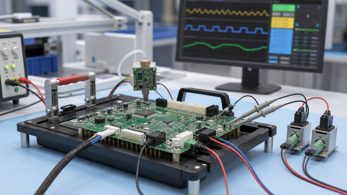
The fixture provides a stable and repeatable connection to the control board so that each production unit can run through the same test procedure under consistent conditions.
Depending on the project, the fixture may connect to:
- power;
- the programming interface;
- sensor-related signals;
- pump and valve driver outputs;
- communication interfaces;
- selected test points.
If the test must simulate pressure-sensor input, additional electrical or pressure-input conditions may also be required.
The fixture itself does not determine what qualifies as a passing result. Production testing still requires a defined test procedure and approved pass/fail criteria.
PCBA Testing Is Not Blood Pressure Monitor Calibration
PCB assembly testing and final-device calibration or validation address different levels of the product.
An assembled control board can pass AOI, electrical checks, firmware programming, and functional testing and still need to complete device assembly, calibration, and validation.
| PCB assembly testing | Final device calibration / validation |
|---|---|
| Checks whether the assembled PCB operates as defined | Checks the final performance of the complete device |
| Examines power, MCU operation, and board-level interfaces | Includes the cuff, pneumatic system, and mechanical structure |
| Verifies the pressure-sensor interface | Verifies final pressure and blood pressure measurement performance |
| Checks pump and valve driver outputs | Verifies the behavior of the complete pneumatic control system |
| Applies board-level pass/fail requirements | Applies device-level performance requirements |
Passing board-level testing means only that the defined PCB functions meet their corresponding test requirements. It does not prove that the finished blood pressure monitor meets final measurement-accuracy requirements.
This boundary is especially important in medical electronics projects. The PCB assembly manufacturer is responsible for board-level manufacturing quality and the test scope agreed by both parties. Final device performance is part of the complete product-design, integration, and validation process.
Prototype vs Production Testing
Testing during the prototype stage will not always look the same as testing in stable volume production.
During an early prototype or engineering build, the team may rely more heavily on engineering instruments, manual probing, and flexible test steps. The immediate purpose is to uncover assembly problems, hardware issues, and testability constraints as early as possible.
As the design stabilizes, the test method can become more standardized. During NPI and production, the process can progressively move toward:
Fixed fixture + controlled firmware + defined procedure + pass/fail criteria
This allows different boards of the same model to be tested repeatedly under equivalent conditions.
For medical electronics, production testing is not limited to deciding whether one board works at a particular moment. It also helps ensure that inspection and test activities are performed and recorded consistently across production lots.
Test Records and Traceability
If the only record after testing is a simple “PASS,” it may be difficult to reconstruct the production state when a later issue is investigated.
Depending on project requirements, the test record for a blood pressure monitor PCB may be associated with:
- PCB revision;
- BOM revision;
- firmware version;
- test-program version;
- test result;
- lot number or serial number;
- nonconformance record, where applicable.
The exact records to retain should be determined by customer requirements, the applicable quality system, and manufacturing documents approved by both parties. For related quality-system context, see ISO 13485 Medical PCB Assembly & Manufacturing.
In medical electronics manufacturing, traceability is useful for more than locating an individual board after a problem occurs. It can also show which PCB revision, firmware version, and test-program version were used for a particular production lot.
That version relationship becomes especially important whenever the design or firmware changes.
Blood Pressure Monitor PCB Assembly Testing Checklist
When developing a test plan for a blood pressure monitor PCB assembly, the team should first confirm the following questions:
- Have the PCB and BOM revisions been confirmed?
- Does the firmware version match the current production release?
- Has the required scope for SPI, AOI, and X-ray inspection been defined?
- Are the pass/fail criteria for power-up and critical electrical checks clear?
- Does the pressure-sensor interface require board-level testing?
- Do the pump and valve drivers require output or load testing?
- Are display, USB, Bluetooth, or other interface tests required?
- Which tests require a dedicated fixture?
- Have the functional-test procedure and pass/fail criteria been approved?
- Must the test result, lot number, or serial number be retained?
- Is the responsibility boundary between PCB assembly testing and final-device calibration clear?
This checklist does not replace the project’s own test specification. It can, however, help the team determine during NPI which tests should be performed at the PCB assembly stage.
From PCB Assembly Testing to the Finished Blood Pressure Monitor
The purpose of blood pressure monitor PCB assembly testing is not to complete every finished-device verification step early. It is to identify board-level problems while the board is still at the PCB manufacturing stage.
The overall flow can be summarized as:
PCB assembly -> inspection -> electrical checks -> firmware programming -> board-level functional testing -> device assembly -> calibration / device-level validation
Finding placement, soldering, programming, sensor-interface, pump or valve driver, and communication-interface problems at board level can prevent affected PCBAs from proceeding into more costly device assembly and troubleshooting.
Final performance still has to be verified with the complete cuff, pneumatic system, firmware, mechanical assembly, and calibration conditions.
The most appropriate role for PCB assembly testing is therefore straightforward:
Keep the problems that can be found at board level at the board level, and reserve full medical-device performance verification for the complete device.
SugaMed provides blood pressure monitor PCB assembly services based on customer-supplied PCB data, BOMs, firmware, inspection criteria, test procedures, and project requirements. The agreed scope may cover PCB/PCBA manufacturing, assembly, inspection, and corresponding board-level testing.