
Resistors are among the most basic and most numerous components on a PCB. They limit current, divide voltage, establish bias points, condition signals, and support circuit protection. A typical PCB assembly may contain only a few major integrated circuits but still use dozens or hundreds of resistors.
Most small resistors used in modern electronics are surface-mount devices. They are commonly called SMT resistors, SMD resistors, or chip resistors. Unlike traditional leaded resistors, they mount directly onto pads on the PCB surface. Their compact size and compatibility with automated placement make them common in smartphones, computers, industrial controls, and medical electronics.
What Is an SMT Resistor
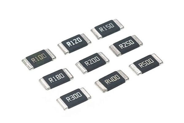
An SMT resistor is a resistor packaged for direct mounting on PCB surface pads using surface-mount technology. Most rectangular chip resistors have a ceramic body, a resistive element, protective coatings, and metal terminations at both ends. During assembly, solder paste is printed onto the pads, the resistor is placed by automated equipment, and the solder is melted during reflow to form the electrical and mechanical connection.
The resistance value, tolerance, temperature coefficient, power rating, voltage rating, package size, pulse capability, and construction all affect whether a resistor is suitable for a particular circuit. Two parts with the same nominal resistance and package can therefore behave very differently in precision, high-voltage, surge, or high-power applications.
Common Types of SMT Resistors
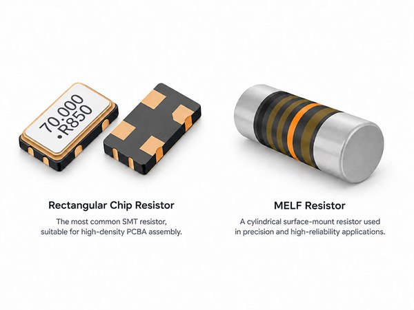
The most common SMT resistor is the rectangular thick-film chip resistor. It usually uses alumina ceramic as the substrate. A thick-film resistive layer is formed on the surface, fired, and laser-trimmed to achieve the required value. Thick-film resistors offer low cost, a wide resistance range, and a mature manufacturing process, making them suitable for general digital circuits and many standard electronic products.
Thin-film resistors use a much thinner resistive layer, commonly formed by vacuum deposition or sputtering. They can provide tighter tolerance and lower temperature coefficient than standard thick-film parts, so they are often selected for precision measurement, analog signal conditioning, and voltage sensing.
MELF resistors are cylindrical surface-mount resistors. They are less common on standard PCBAs than rectangular chip resistors but remain useful in precision, high-reliability, and high-voltage applications. Other specialized SMT resistor families include low-resistance current-sense resistors, surge-resistant resistors, high-power parts, and wide-terminal designs.
SMT Resistor Sizes and Package Codes
Chip resistors are typically classified by body length and width. The industry uses both imperial and metric size codes, so the same physical package can have two different identifiers. For example, an imperial 0603 resistor has nominal dimensions of approximately 1.6 × 0.8 mm and corresponds to metric size 1608.
| Imperial size | Metric size | Nominal dimensions |
|---|---|---|
| 01005 | 0402 | 0.4 × 0.2 mm |
| 0201 | 0603 | 0.6 × 0.3 mm |
| 0402 | 1005 | 1.0 × 0.5 mm |
| 0603 | 1608 | 1.6 × 0.8 mm |
| 0805 | 2012 | 2.0 × 1.25 mm |
| 1206 | 3216 | 3.2 × 1.6 mm |
| 1210 | 3225 | 3.2 × 2.5 mm |
Package dimensions and tolerances should always be confirmed in the component manufacturer’s datasheet. Smaller packages allow more devices to fit into the same PCB area, but they also narrow the manufacturing process window. If board space is not severely constrained, replacing every 0603 resistor with a 0201 may add unnecessary demands on land-pattern design, solder paste printing, placement accuracy, and reflow control.
Package Size and Power Rating
Larger packages often support higher power ratings, but package size and power rating are not equivalent. Traditional references commonly cite approximately 1/20 W for 0201, 1/16 W for 0402, 1/10 W for 0603, 1/8 W for 0805, and 1/4 W for 1206 standard chip resistors. These are only general reference values.
Modern product families include high-power, wide-terminal, and thermally optimized versions. Even two 0603 resistors can have different power ratings. The correct design approach is to check the datasheet for the exact part number, including rated power, maximum working voltage, overload rating, and the temperature derating curve. At elevated operating temperatures, the allowable continuous power is usually reduced.
How to Read SMT Resistor Markings
Larger chip resistors often have printed resistance codes. With a three-digit code, the first two digits are significant figures and the third digit is the number of zeros. For example, 103 means 10 × 1,000 = 10,000 Ω, or 10 kΩ, while 114 means 110 kΩ.
- 5R6 means 5.6 Ω.
- R39 means 0.39 Ω.
- 000 normally identifies a 0 Ω jumper resistor. It is not literally zero resistance; the part is commonly used for bridging, configuration options, testing, or circuit selection.
The letter R replaces the decimal point for values below 10 Ω or values that contain a decimal. Precision parts may use four-digit markings or EIA-96 codes. Very small packages such as 0402, 0201, and 01005 often have no printed value, so identification depends on the BOM, manufacturer part number, and reel label.
Key Specifications for Selecting an SMT Resistor
A description such as 10 kΩ, 0603 is not enough to complete resistor selection. For ordinary pull-up, pull-down, or LED current-limiting applications, a standard thick-film resistor with ±1% or ±5% tolerance may be sufficient. Precision voltage division, voltage sensing, and analog measurement require closer attention to several specifications:
- Resistance tolerance: sets the initial allowable deviation from the nominal value.
- Temperature coefficient of resistance: is commonly specified in ppm/°C or ppm/K and indicates how much the resistance can change with temperature.
- Power rating and derating: determine how much heat the part can dissipate under the stated conditions.
- Maximum working voltage: can be exceeded even when calculated power remains within the rated limit.
- Pulse and surge capability: matters when the circuit experiences brief high-current or high-energy events.
Designers normally leave thermal and electrical margin rather than operating a resistor continuously at its limit. In high-voltage dividers, power-input circuits, or high-resistance applications, it may be necessary to use high-voltage parts or several resistors in series to share the voltage. Components that look identical can have very different transient-energy ratings, so appearance is not a reliable basis for substitution.
How Small Resistors Affect SMT Assembly
Modern equipment can place common 0805 and 0603 resistors quickly and reliably. The process becomes more demanding with 0201 and 01005 packages. These parts are more sensitive to feeder and nozzle condition, placement accuracy, PCB flatness, stencil aperture design, solder paste transfer, land-pattern symmetry, and surrounding copper geometry.
Tombstoning is a typical small-component defect. During reflow, one end of the resistor can lift when the solder at the two ends wets at different times or develops unbalanced surface tension. Contributing factors include asymmetric pads, unequal paste volumes, large differences in copper area, and variations in the thermal profile. The complete SMT production line must therefore be considered rather than assuming that placement alone caused the defect.
As component size decreases, process inspection becomes more important. An appropriate PCB assembly inspection and testing plan can combine SPI, AOI, X-ray inspection when required by package type and risk, and electrical or functional tests defined for the product.
High-Power and Current-Sense Resistors
High-power resistors affect not only their own temperature but also the pads, copper traces, and PCB. Pad dimensions, copper area, clearance from nearby components, airflow, and board thermal performance influence the final temperature rise. Temperature sensors, voltage references, and other sensitive components should not be placed nearby without evaluating thermal coupling.
Low-resistance current-sense resistors create a different challenge. Their resistance may be only a few milliohms, so the resistance of PCB copper, pads, and solder joints can no longer be ignored. High-accuracy current measurement often uses Kelvin four-wire connections that separate the high-current path from the voltage-sensing path, reducing measurement error caused by interconnect resistance.
Why Chip Resistors Have Metal Terminations
The ends of a rectangular chip resistor normally contain several metal layers rather than a single metal coating. A simplified structure is internal electrode → nickel barrier → external tin finish. The internal electrode connects the resistive element to both ends of the component. The nickel barrier helps limit diffusion and dissolution of the inner electrode materials during soldering, while the outer tin finish provides solderability.
Most standard commercial chip resistors now use lead-free terminations, commonly a nickel barrier with matte tin. Older references may show tin-lead terminations, but these are no longer the mainstream finish for standard commercial electronics. The exact termination construction should still be checked in the manufacturer’s specification when regulatory, solderability, or reliability requirements are critical.
What Is an SMT Resistor Array
A resistor array or resistor network integrates multiple resistors into one package. For example, 8P4R commonly indicates eight pins and four internal resistors. The elements may be independent or may share a common terminal. Arrays are often used for pull-up and pull-down networks, digital interfaces, and circuits that require several equal-value resistors.
Replacing several individual parts with one array can reduce placement count and save PCB area, but the internal connection cannot be determined from package appearance alone. Two networks that look nearly identical may have different circuit topologies, so the schematic, pinout, and datasheet must be checked before selection or substitution.
Conclusion
SMT resistors may look simple, but selecting the right part involves more than choosing a resistance value and package. Thick-film, thin-film, MELF, high-voltage, current-sense, surge-resistant, and high-power resistors address different electrical and manufacturing requirements.
Package size also involves a tradeoff. Moving from 0603 to 0201 can save PCB area, but it increases the demands on pad design, paste printing, placement, reflow, and inspection. Reliable selection balances electrical performance, thermal margin, board space, manufacturing capability, availability, and cost, using the exact component datasheet as the final authority.