
Medical electronics—from patient monitors and blood pressure monitors to portable diagnostic devices, anesthesia systems, dialysis equipment, and therapeutic devices—depend on PCB assemblies for signal acquisition, data processing, power management, communication, and control.
Medical PCB assembly uses many of the same manufacturing processes found in other electronics, including solder paste printing, SMT placement, reflow soldering, AOI, X-ray inspection, and electrical and functional testing.
The main difference is how the manufacturing process is controlled. A medical device may remain in production for years, during which BOMs are updated, components become obsolete, PCB designs change, firmware is revised, and test programs evolve. Manufacturing records must be able to support ongoing production, engineering changes, and later investigations.
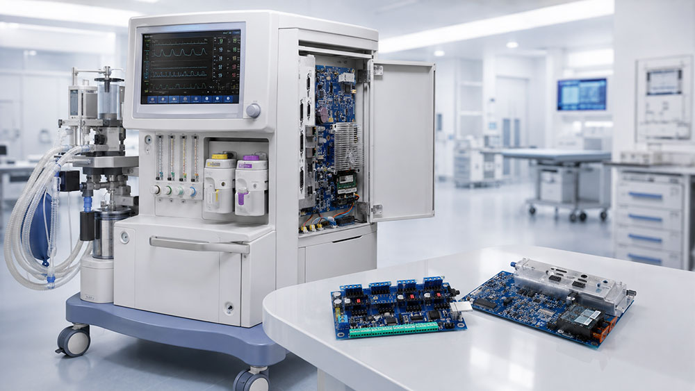
For that reason, medical PCB assembly extends well beyond SMT production. It often involves manufacturing documentation, PCB fabrication, component sourcing, SMT and THT assembly, inspection, testing, and production traceability.
This guide explains how those steps fit together, how different PCB constructions affect assembly, which inspection methods are used, and what medical device OEMs should consider when moving from prototype to production.
What Is Medical PCB Assembly?
Medical PCB assembly, also referred to as medical PCBA or medical device PCB assembly, is the process of mounting and soldering electronic components onto printed circuit boards used in medical electronics, followed by the required inspection, programming, and testing.
A complete project may include PCB fabrication, component sourcing, SMT assembly, THT assembly, programming, inspection, and functional testing. The exact manufacturing route depends on the product design.
A compact portable medical device, for example, may use 0201 or 01005 passives, fine-pitch QFNs, and BGAs. These designs place greater emphasis on solder paste control, placement accuracy, and inspection of hidden solder joints.
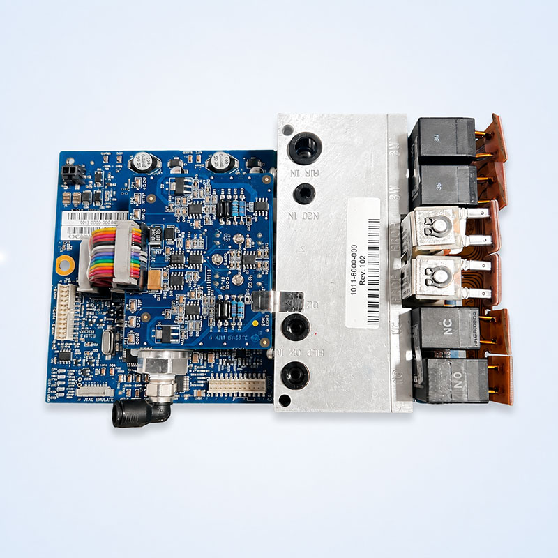
A larger medical control board may instead contain large connectors, transformers, relays, and through-hole components. Its manufacturing challenges may involve through-hole soldering, mechanical connections, and functional testing.
Medical PCB assembly describes an application area, not a fixed PCB construction or a single set of process parameters that applies to every medical product.
How Is Medical PCB Assembly Different From Standard PCB Assembly?
Medical electronics still rely on common SMT and THT technologies. The differences usually come from product risk, operating environment, product life cycle, and the OEM’s manufacturing and quality requirements.
Reliability requirements depend on the device
A home blood pressure monitor, a patient monitoring system, a portable diagnostic instrument, and a therapeutic device operate under very different conditions and have different consequences of failure.
Reliability levels and acceptance criteria should be defined according to the intended use of the product and the customer’s requirements.
Medical PCBA does not automatically mean IPC Class 3.
Some high-reliability projects may specify Class 3, while other medical electronics may be manufactured to Class 2 according to approved project documentation. The applicable acceptance class should be established before production begins.
Components and materials need controlled management
Medical products often have long life cycles, making EOL, NRND, and component substitution common concerns.
If an MCU becomes obsolete, a replacement with similar headline specifications may still affect the footprint, power architecture, firmware, programming process, or functional test.
Once an alternate component is approved, the BOM, design documentation, and relevant test requirements may also need to be updated.
Moisture-sensitive devices such as BGAs and QFNs may also require appropriate MSL, packaging, storage, and floor-life controls.
Component obsolescence can affect far more than one line in the BOM.
When a critical MCU, power IC, or sensor reaches EOL, the replacement may require another review of the PCB footprint, firmware, programming method, test program, and first-article requirements.
These changes are best handled through a controlled change process. Updated documentation should identify when the new configuration enters production, such as by production lot or serial number range. This makes it much easier to distinguish pre-change and post-change assemblies if an issue is discovered later.
Inspection and testing need defined coverage
AOI, X-ray, ICT, and FCT are designed to find different types of problems.
AOI examines visible components and solder joints. X-ray provides visibility into hidden joints such as those beneath BGAs. ICT or flying probe testing checks selected electrical networks, while FCT verifies specified functions under defined operating conditions.
The inspection plan should match the PCB structure and the defects the project is trying to detect.
Traceability needs to support investigation
A production date alone is rarely enough for a meaningful failure investigation.
Depending on the project, traceability may include the PCB manufacturing lot, critical component lots, BOM revision, firmware version, test program revision, and records of rework or deviations.
When failures are concentrated around one component lot or one software revision, these records can narrow the investigation considerably.
Medical PCB Assembly Process
Medical PCBA production normally starts with documentation and manufacturing preparation—not with the pick-and-place machine.
1. Design and Manufacturing Review
Before production, the manufacturer should confirm that the manufacturing package is complete and that all files belong to the same released revision.
Typical inputs include:
Gerber or ODB++ data, BOM, pick-and-place files, assembly drawings, programming files, test specifications, and any special process requirements.
A common issue is a BOM that has already been updated while the assembly drawing still shows an older revision. Another example is an approved alternate component that has not yet been reflected in the placement or test files.
DFM review looks at pads, stencil requirements, panelization, fiducials, component spacing, vias, and structures such as BGAs and QFNs to determine whether the design is suitable for manufacturing.
DFT focuses on test-point access, ICT or flying-probe accessibility, and the interfaces required for functional testing.
These issues are usually easier to correct during the design stage. Once PCBs, stencils, or test fixtures have already been built, even a small change can affect several downstream processes.
2. PCB Fabrication and Component Sourcing
After the manufacturing review, the bare PCBs and BOM components can be prepared.
Medical electronics may use conventional multilayer rigid boards, HDI, flex, rigid-flex, or specialty-material PCBs. The board construction is driven by electrical, mechanical, and space requirements.
Component sourcing should verify the manufacturer part number, package, specification, quantity, and BOM revision.
Long-life products also benefit from an early review of critical-component availability. If an IC is already NRND or approaching EOL, it may create supply risk even if enough parts are still available for prototype builds.
Turnkey PCB assembly can help coordinate PCB fabrication, sourcing, and assembly around the same controlled manufacturing package, reducing information mismatches between multiple suppliers.
3. Solder Paste Printing and SPI
Many SMT soldering defects begin during solder paste printing.
Stencil thickness, aperture design, PCB pad geometry, and paste release all influence solder deposition.
A single board may contain miniature passives, fine-pitch ICs, QFN thermal pads, and much larger components. These features do not necessarily require the same solder paste volume.
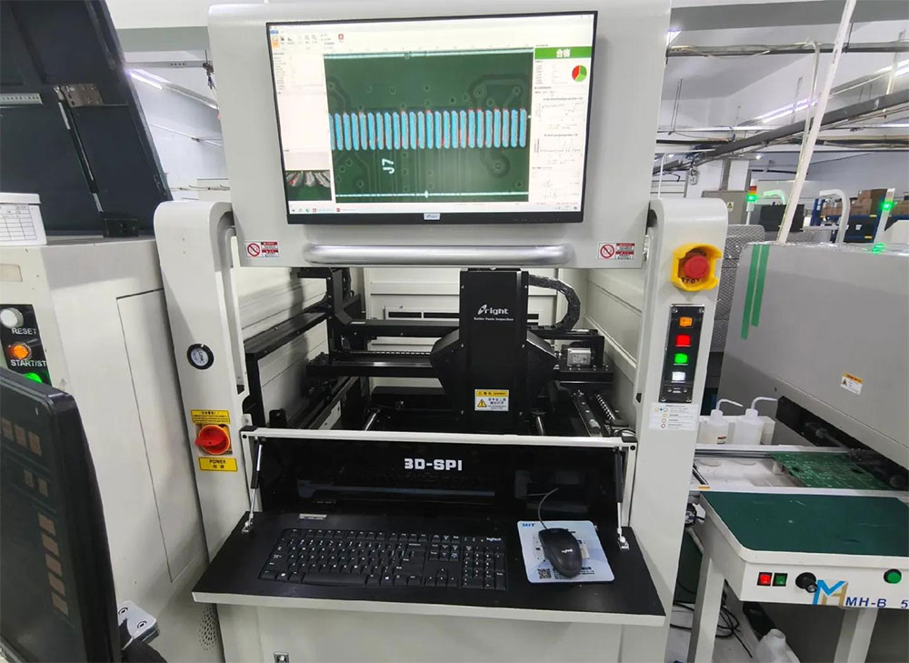
3D SPI can measure solder paste height, area, volume, and positional offset before component placement.
SPI is useful for more than rejecting individual boards. Trend data can also show whether the printing process is beginning to drift. If paste volume at the same location gradually decreases, the process can be checked for stencil cleaning, printing parameters, or equipment-related causes.
4. Component Placement
After SPI, the pick-and-place machine positions components according to the approved placement program.
Portable, handheld, and wearable medical electronics increasingly use QFNs, BGAs, fine-pitch ICs, and very small passive components.
SugaMed’s current SMT platform supports components down to 01005 and can handle 0.35 mm pitch BGA and QFN packages.
Machine specifications define the capability of the manufacturing platform, but they do not determine the outcome by themselves. PCB fiducials, board warpage, land patterns, component packaging, nozzle selection, and machine programming can all affect placement performance.
5. Reflow Soldering
After placement, the PCB enters the reflow oven.
A typical reflow profile includes preheat, soak, reflow, and cooling stages.
The appropriate profile depends on the solder paste, PCB thickness, copper distribution, component thermal mass, and package construction.
If a board contains a large connector, a BGA, and miniature passive components, different areas of the PCB may heat at noticeably different rates. The actual temperatures measured at critical locations on the board are more useful than the oven’s set temperatures alone.
There is no universal “medical PCB reflow temperature.”
Nitrogen reflow is also a project-specific process choice. Its use depends on the solder system, oxidation-control needs, and product requirements.
6. AOI and X-Ray Inspection
Post-reflow AOI is commonly used to inspect the assembled board.
AOI is effective for detecting missing components, placement offsets, polarity errors, and many visible solder-joint defects.
BGAs and some bottom-terminated packages have solder connections underneath the component, where AOI has limited or no direct visibility. X-ray inspection provides additional coverage for these joints.
X-ray can help identify BGA bridging, missing balls, some voiding, and significant alignment issues. Electrical and functional performance still need to be verified by other test methods.
For SugaMed’s current manufacturing process, prototype SMT assemblies receive 100% post-reflow AOI, and BGA solder joints receive 100% X-ray inspection. Inspection coverage for other bottom-terminated packages such as QFNs and LGAs is defined according to package construction and project requirements.
7. THT and Secondary Assembly
Many medical PCBs still include through-hole components.
Large connectors, transformers, switches, relays, and components that require additional mechanical strength may use THT mounting.
Depending on the PCB and component design, the assembly process may use selective soldering, wave soldering, pin-in-paste, or manual soldering.
Some products also require cable installation, heat sinks, shielding, or other secondary assembly operations.
8. Electrical and Functional Testing
After soldering and visual inspection, the PCBA can move into electrical and functional testing.
ICT or flying probe testing can detect opens and shorts and verify selected component values or electrical networks. Coverage depends in part on DFT and test-point accessibility.
FCT verifies PCBA behavior under defined power, input, load, or interface conditions. Depending on the design, this may include power outputs, communication interfaces, sensor inputs, or control signals.
Products that require firmware can also be programmed at the appropriate stage of production.
PCBA-level FCT verifies only the functions defined in the test specification. It does not replace system-level, safety, or regulatory validation of the finished medical device.
9. Final Inspection and Release
Before shipment, the assembly may undergo final checks for appearance, test status, labels, serial numbers, firmware version, rework status, and packaging requirements.
If the project requires traceability, production lot, PCB lot, critical component lots, PCBA serial number, firmware, and inspection or test records can also be linked at this stage.
The PCBA is released for packaging and shipment once the defined acceptance criteria have been met.
Inspection and Testing for Medical PCB Assemblies
Different inspection methods cover different types of defects.
| Inspection / Test | What It Checks | Main Limitation |
|---|---|---|
| SPI | Solder paste height, area, volume, and positional offset | Does not verify post-reflow solder joints or product function |
| AOI | Missing or shifted components, polarity, and many visible solder-joint defects | Cannot directly inspect hidden BGA connections |
| X-Ray | BGA, QFN/LGA bottom-side connections, bridging, some voiding, and alignment issues | Does not replace electrical or functional testing |
| ICT / Flying Probe | Opens, shorts, selected component values, and network status | Coverage depends on test access and DFT |
| FCT / ATE | PCBA operation under defined inputs, loads, and software conditions | Coverage is limited to the test program |
For example, an internal BGA short is better suited to X-ray inspection, while a missing component is normally detected by AOI. Communication interfaces or sensor functions require functional testing.
For more complex products, the test strategy can be mapped as:
Potential defect → Inspection/Test method → Coverage → Pass/Fail criteria → Reaction
This provides a much clearer picture of test coverage than simply comparing the number of inspection machines in a factory.
What Standards Apply to Medical PCB Assembly?
Several commonly referenced standards address different parts of the manufacturing and quality system.
| Standard / Regulation | Relevance to Medical PCB Assembly | It Does Not Mean |
|---|---|---|
| ISO 13485:2016 | Medical-device quality management system covering areas such as documentation, suppliers, production, records, and traceability | An individual PCB is “ISO 13485 certified” |
| IPC-A-610J | Acceptance criteria for completed electronic assemblies | Every medical PCBA must be Class 3 |
| J-STD-001J | Process and material requirements for soldered electrical and electronic assemblies | One fixed set of “medical soldering” parameters |
| FDA QMSR | U.S. medical-device quality system regulation, effective February 2, 2026, incorporating ISO 13485:2016 by reference | Every PCB assembly supplier is an “FDA-certified manufacturer” |
For a PCBA project, ISO 13485 is primarily related to the quality management system and manufacturing controls. IPC-A-610 and J-STD-001 are more directly connected to electronics assembly processes and acceptance.
The applicable IPC class should be determined by the product, customer specifications, and approved project documentation.
A PCBA supplier supports controlled manufacturing within its contractual and manufacturing scope. Regulatory responsibilities for the finished medical device depend on the organization’s role in the medical-device supply chain.
PCB Types Used in Medical Electronics
Medical devices use different PCB constructions depending on size, signal requirements, mechanical design, and interconnect density.
| PCB Type | Typical Applications | Assembly Considerations |
|---|---|---|
| Rigid PCB | Control boards, power boards, interface boards, patient monitoring and laboratory equipment | Mature manufacturing process; well suited to automated SMT and THT |
| HDI PCB | Compact diagnostic devices, portable medical electronics, high-density control boards | Fine-pitch printing, placement, reflow, and hidden-joint inspection |
| Flex PCB | Wearable devices, sensors, probes, and space-constrained interconnects | Fixturing, panel handling, and protection of flexible areas |
| Rigid-Flex PCB | Folded assemblies, connector reduction, and space-constrained products | More demanding assembly support, handling, and rework |
| Special-Material PCB | RF, wireless, imaging, or specialized sensor electronics | Material properties may affect both PCB fabrication and assembly |
PCB construction is primarily driven by product design.
HDI, for example, is a PCB fabrication technology, but higher interconnect density often comes with smaller components, tighter pitches, and less manufacturing margin. That can narrow the assembly process window as well.
Common Applications of Medical PCB Assemblies
Medical PCB assemblies are used across devices that require sensing, control, display, communication, or data processing.
| Application | Typical Electronics | PCBA Manufacturing Focus |
|---|---|---|
| Patient Monitoring Equipment | ECG, SpO2, NIBP, temperature, communication, and display | Mixed-signal performance, connection reliability, functional testing |
| Blood Pressure Monitors | Pressure sensors, analog front end, MCU, power, and display | Sensor inputs, low-power operation, production consistency |
| Diagnostic Equipment | High-speed digital, mixed-signal circuits, BGAs, and complex I/O | High-density SMT, X-ray inspection, test coverage |
| Portable / Wearable Devices | Miniaturization, low power, HDI, flex, or rigid-flex | Fine-pitch assembly, DFM, handling, and test access |
| Anesthesia Equipment | Control, sensing, display, communication, and power modules | Different boards may require different inspection and test strategies |
| Hemodialysis Equipment | Pumps, sensors, control, power, and HMI | Long-term production, revision control, and test records |
A single medical device may contain several different PCB assemblies.
For example, the acquisition board, power board, and communication board inside a diagnostic system have different circuit functions and do not necessarily need the same assembly and testing conditions.
Application-specific pages can go deeper into these individual systems. This guide keeps the focus on the manufacturing considerations needed to understand medical PCB assembly as a whole.
From Prototype to Production
A working prototype verifies important parts of the design, but volume production also requires a repeatable manufacturing process.
Prototype builds often involve more manual intervention, such as repositioning components, local rework, firmware changes, or temporary adjustments to the test procedure.
When production grows from five or ten boards to hundreds or thousands, those temporary fixes need to be converted into controlled production conditions.
Typical items to confirm include:
- BOM and PCB revision
- Stencil and placement program
- Reflow profile
- Inspection coverage
- Programming version
- Test program and acceptance criteria
First Article Inspection
First Article Inspection is more than checking whether the first assembled board powers up or functions correctly.
FAI can also confirm that the current manufacturing files, critical materials, production programs, and test conditions are aligned.
Depending on the project, first-article verification may include SPI, AOI, X-ray, electrical testing, functional testing, and programming results. The purpose is to confirm that the material set, manufacturing process, and test method are ready for continued production.
If the first article still requires repeated manual adjustment, extensive rework, temporary programming changes, or subjective engineering judgment to pass testing, the production process may need further refinement.
Significant changes to the PCB revision, BOM, stencil, critical components, firmware, or test program may also require another first-article review.
The goal of prototype-to-production transfer is to reduce dependence on manual intervention and establish a process that can be repeated consistently.
What Should You Prepare Before Starting a Medical PCBA Project?
Before requesting a quotation, DFM review, or prototype assembly, it helps to prepare the basic manufacturing package.
| File / Information | Main Purpose |
|---|---|
| Gerber / ODB++ | PCB fabrication and manufacturing review |
| BOM | Component sourcing, part-number verification, and revision control |
| Pick-and-Place / CPL | SMT placement-program preparation |
| Assembly Drawing | Component position, polarity, and assembly requirements |
| PCB Specification | Layer count, materials, surface finish, and other PCB requirements |
| Expected Quantity | Prototype and production planning |
If programming and testing requirements are already defined, the package can also include firmware, test specifications, acceptance criteria, approved substitution rules, traceability requirements, and special inspection requirements.
The earlier these requirements are defined, the more effectively DFM, DFT, and manufacturing preparation can be completed before production begins.
Conclusion
Medical PCB assembly covers much more than component placement. It brings together PCB fabrication, component sourcing, SMT and THT assembly, inspection, testing, and production-record control.
Each inspection method covers a different part of the process. SPI focuses on solder paste printing, AOI finds many visible assembly defects, X-ray provides visibility into hidden solder joints, ICT and flying probe test electrical networks, and FCT verifies defined functions.
The manufacturing and inspection route should be selected according to the PCB construction, component packages, product requirements, and likely failure modes.
SugaMed can support medical electronics projects with PCB fabrication coordination, component sourcing, SMT and THT assembly, BGA inspection, ICT/FCT/ATE, programming, DFM, and NPI support.
If your project already has Gerber or ODB++ data, a BOM, pick-and-place files, assembly drawings, and test requirements, these files can be reviewed before production to identify issues that may affect assembly or testing later.