
Selecting High Tg PCB material comes down to one question: does the board’s assembly process, operating environment, or service life create enough thermal-mechanical stress that standard FR4’s Tg 130–140°C no longer provides adequate margin?
If the answer is no — single reflow pass, low layer count, operating temperature well below 80°C — standard or mid-Tg FR4 at 150°C is the more cost-effective choice. High Tg PCB (typically Tg 170°C or higher) costs 20–40% more than standard FR4 and may require tighter fabrication controls. That premium is only justified when there is a specific failure mode it prevents.
内容
- What Thermal Conditions Actually Justify High Tg
- Automotive and Industrial Boards: The Case for Tg 170°C+
- High Layer Count and HDI: Why Via Reliability Drives the Tg Decision
- Power and LED Boards: High Tg Helps, But It Does Not Remove Heat
- When Standard FR4 Is the Better Choice
- Turning the Decision Into an RFQ Callout
What Thermal Conditions Actually Justify High Tg
The decision starts with what the laminate will actually experience — not with material categories.
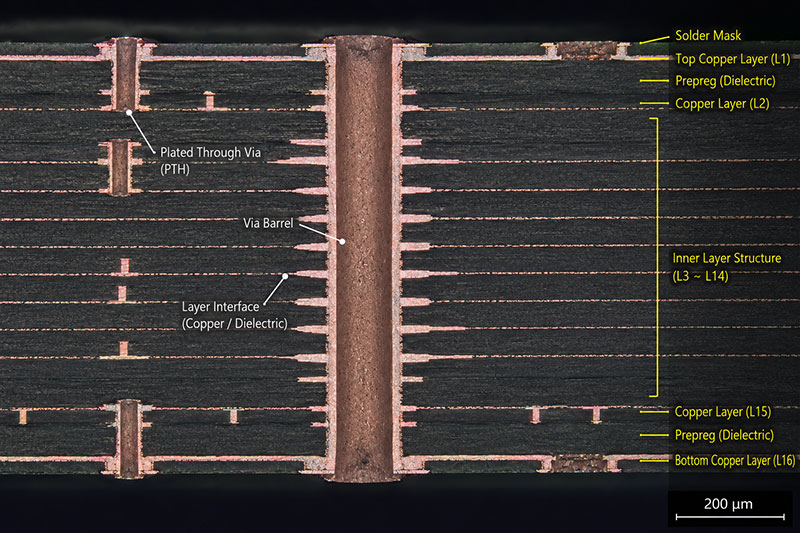
Above Tg, the z-axis CTE of an epoxy laminate rises sharply: typically from 50–70 ppm/°C below Tg to 200–300 ppm/°C above it. That expansion is what cracks via barrels, delaminates inner layers, and initiates CAF failures in dense boards. The laminate does not instantly fail above Tg, but each thermal cycle that crosses the threshold accumulates damage.
The conditions that most commonly trigger High Tg specification:
| Stress Condition | Why It Matters |
|---|---|
| Two or more lead-free reflow cycles at 245–260°C | Thermal stress accumulates; each cycle compounds z-axis fatigue |
| Operating temperature above 85°C sustained | Long-term exposure erodes margin between operating temp and Tg |
| 8+ layer stackup | More interfaces increase interlayer delamination risk |
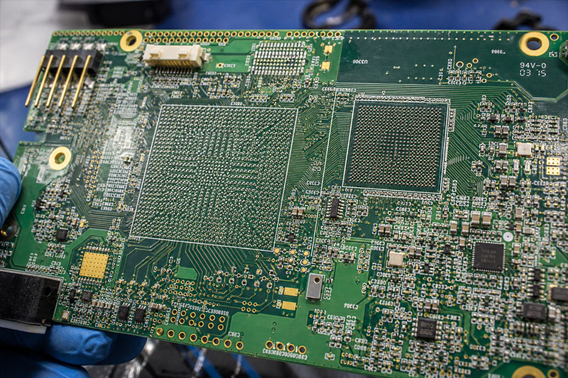
| BGA or dense via fields | Via barrels and pads see concentrated thermal-mechanical stress |
| Board thickness above 2.4 mm | Longer via barrels absorb more z-axis expansion per cycle |
| Long service life or IPC Class 3 target | Less tolerance for material substitution or marginal laminate behavior |
A single condition from this list does not always justify High Tg. A 12-layer board operating at room temperature with one reflow pass is different from an 8-layer board running at 95°C through three reflow cycles. The decision requires looking at the combination.
Automotive and Industrial Boards: The Case for Tg 170°C+
The case for Tg 170°C+ in automotive and industrial applications is not reflow survival — it is long-term operating stability under repeated thermal cycling.
Thermal Cycling Accumulates Fatigue
An automotive ECU in an under-hood location may see ambient temperatures from –40°C to +105°C. Add self-heating from power components, and junction temperatures inside the board can swing 80–100°C per cycle. Over 10–15 years, a standard FR4 laminate at Tg 135°C crosses its glass transition repeatedly. Each crossing drives z-axis expansion that strains via barrels and inner-layer interfaces. High Tg FR4 at 170°C keeps the laminate in its stiffer, lower-expansion state through more of that thermal range.
Heavy Copper Weight Adds Lamination Stress
Industrial power boards commonly use 2 oz, 3 oz, or 4 oz copper for current-carrying traces and thermal planes. Copper’s CTE mismatch with epoxy resin creates internal shear stress during thermal cycling. The stiffer resin system in High Tg laminates reduces differential movement between copper and resin — relevant for motor drive boards and inverters where thick copper and sustained heat are both present.
Rework Exposure Is Often Underestimated
BMS boards returned for field diagnosis and motor drive assemblies repaired under warranty see rework — localized heat above 260°C, sometimes more than once. Standard FR4 that has already gone through production reflow may show measling, delamination, or CAF initiation after rework. High Tg materials tolerate additional thermal exposure more reliably.
For automotive programs, laminate families such as Shengyi S1170, Isola 370HR, and Panasonic R-1566W offer both higher Tg and higher Td (decomposition temperature, measured by TGA). Tg and Td are not the same: Tg measures softening onset, Td measures when the resin chemically degrades. For rework and extended field life, both matter — a laminate with Tg 170°C but low Td may still delaminate under repeated high-temperature exposure.
A practical threshold used by many PCB engineers: if operating temperature will spend significant time above 110°C, or if the board will see more than four total reflow-equivalent heat cycles, Tg 170°C+ is the default starting point. Below those thresholds, mid-Tg FR4 at 150–155°C often covers the risk at lower material cost and without narrowing the supplier pool.
High Layer Count and HDI: Why Via Reliability Drives the Tg Decision
In multilayer and HDI boards, High Tg is often chosen for via reliability rather than ambient operating temperature. The board structure creates the stress condition even when the environment does not.
Aspect Ratio Determines Via Barrel Risk
Aspect ratio is board thickness divided by drill diameter. A 2.4 mm board with a 0.3 mm drill produces an 8:1 aspect ratio. IPC-6012 Class 3 acceptance criteria become difficult to meet consistently above 10:1. When the laminate expands in the z-axis during reflow, a via barrel at high aspect ratio is pulled in tension along its full length. High Tg laminate reduces z-axis expansion below Tg, which directly reduces that tensile load during thermal cycling.
Sequential Lamination Adds Thermal History Before Assembly Begins
HDI boards with blind and buried vias go through the lamination press multiple times before final drilling and SMT assembly. By the time the board reaches lead-free reflow, inner layer interconnects have already absorbed several high-temperature fabrication cycles. High Tg core materials hold up better through repeated press cycles — incoming laminate Tg alone does not describe the finished board’s cumulative thermal exposure.
Server and Telecom Boards Combine High Layer Count With Long Runtime
Backplanes and compute boards at 16–32 layers may see 8–12 reflow and press cycles through the complete manufacturing process, then operate for years in environments where server inlet temperatures reach 40–45°C with significant board self-heating. Via reliability — not surface temperature — is the dominant failure mode for these designs, and High Tg material is standard practice.
Via-in-Pad Structures Require a Stable Laminate Foundation
1.0 mm and 0.8 mm pitch BGAs in server ASICs and FPGAs require resin-filled, capped vias directly under pads. The fill resin and surrounding laminate must not delaminate from pad copper during or after reflow. High Tg laminate reduces the risk of that interface failure.
One factor specific to high-speed telecom boards: some High Tg laminates — particularly halogen-free variants — have slightly different dielectric properties than standard FR4. For boards running 28 Gbps+ serial links, verify Dk and Df at operating frequency in addition to Tg and CTE values. Thermal-mechanical stability and signal integrity are separate requirements that both need to be satisfied.
Power and LED Boards: High Tg Helps, But It Does Not Remove Heat
High Tg does not dissipate heat. It improves the laminate’s resistance to thermal-mechanical stress. These are different problems, and confusing them leads to misspecification in both directions.
What High Tg Does for Power Boards
If a board operates with local temperatures above 110–120°C — near a transformer, under a high-side FET, or below a non-isolated LED array — High Tg FR4 reduces the risk of localized laminate softening, warpage, and delamination. It keeps the resin stiffer at operating temperature, which maintains via integrity and dimensional stability in the affected area.
What High Tg Does Not Do
FR4 has a thermal conductivity of approximately 0.3–0.4 W/m·K regardless of Tg grade. High Tg FR4 does not meaningfully change that value. If heat must be conducted away from a component and into a heatsink or ambient air, the Tg specification is irrelevant to that heat path.
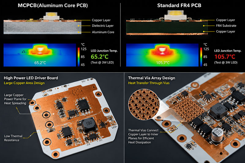
When heat removal is the real problem, the solution is thermal design:
- Thermal via arrays (0.3 mm drills on 0.6 mm pitch) under heatsink pads can reduce thermal resistance by 3–5°C/W in typical configurations.
- Heavy copper planes (2–4 oz) spread heat laterally and reduce spreading resistance.
- Metal Core PCB (MCPCB) uses an aluminum or copper core with a thin dielectric, achieving 1–4 W/m·K thermal conductivity — a fundamentally different construction from FR4, and the correct answer when LED junction temperature must be tightly controlled.
A useful decision boundary: if a power board dissipates more than 2–3 W/cm² locally, address the thermal path first (MCPCB, thermal vias, heatsink). Then assess whether the remaining operating temperature still warrants High Tg laminate for laminate stability. For LED boards below 1 W per emitter with adequate copper pours and thermal vias, standard FR4 at Tg 140°C frequently meets reliability requirements without the added cost.
When Standard FR4 Is the Better Choice
High Tg material adds cost and may reduce the fabricator pool. It is not the right choice when the board does not face the stress conditions that justify it.
Standard FR4 or mid-Tg FR4 at 150°C is usually sufficient when:
- 2–4 layer board — Short via barrels at low aspect ratio see minimal z-axis expansion stress.
- Single lead-free reflow cycle — One thermal event does not accumulate the fatigue damage that multiple cycles create.
- Operating temperature below 80°C — The laminate stays well below Tg in service. Z-axis CTE remains in the lower, stable range.
- No dense BGA or fine-pitch via structures — LQFP packages, through-hole connectors, and standard 0402 passives do not create the via stress concentration that makes High Tg material relevant.
- Service life of 2–3 years — Thermal-mechanical fatigue accumulates over time. Short-life consumer products tolerate more material margin than industrial equipment rated for 15 years.
The clearest signal of overspecification: High Tg is selected because it is “safer” without identifying a specific failure mode it prevents. That reasoning would also justify Rogers 4350B for every analog circuit. Material selection should trace to a failure mode, not to a general preference for higher-rated material.
| Board Condition | Practical Material Direction |
|---|---|
| 2-layer low-power board, single reflow | Standard FR4 |
| 4-layer board, single lead-free reflow | Standard or mid-Tg FR4 |
| Double-sided SMT with rework exposure | Mid-Tg or High Tg depending on layer count and copper weight |
| 8+ layers or dense BGA fanout | Evaluate High Tg based on aspect ratio and cycle count |
| HDI with sequential lamination | High Tg core material; confirm fabricator has validated the lamination sequence |
| Automotive, industrial, or long-service-life boards | Tg 170°C+ with Td review; document approved laminate grades |
| Primary problem is component heat removal | Thermal design first — MCPCB, vias, copper weight; then assess Tg need |
Turning the Decision Into an RFQ Callout
Once High Tg is justified, the drawing note needs to be specific enough that the fabricator cannot substitute a lower-grade laminate and still technically comply.
“High Tg FR4” without further detail is not a specification. A stronger callout includes:
- Minimum Tg value and test method: for example, Tg ≥ 170°C by DSC per IPC-TM-650 2.4.25 or Tg ≥ 165°C by TMA per IPC-TM-650 2.4.24 — TMA values run 5–10°C lower than DSC for the same laminate, so the method must be stated
- Approved laminate grades by name: Isola 370HR, ITEQ IT-180A, Shengyi S1170, or approved equivalent with prior written confirmation
- Substitution clause: no material change without written engineering approval; the Certificate of Conformance must identify the actual laminate brand and grade, not just “High Tg FR4”
Common mistakes at this stage: specifying Tg without the test method, approving “or equivalent” without defining the equivalency criteria, and accepting a CoC that lists only a material category. Any of these gives the fabricator room to use a laminate that meets a loose definition of High Tg while differing in Td, T260/T288, CAF resistance, or z-axis CTE.
For a complete RFQ specification — Td, T260/T288, Z-axis CTE, CAF resistance, IPC Class callout, stackup documentation, and fabricator qualification questions — see the [High Tg PCB Fabrication and RFQ Specification Guide].