
FR4 is the default PCB material for good reason — it is reliable, widely available, and cost-effective for most applications. But some designs push beyond what FR4 can handle: repeated high-temperature reflow cycles, circuits that need to bend inside a compact enclosure, or assemblies that must remain stable under sustained heat. This is where polyimide becomes the practical choice.
Table of Contents
What Is a Polyimide PCB?
A polyimide PCB uses polyimide (PI) as the base dielectric material instead of the more common FR4 epoxy-glass laminate. The distinction matters in one specific situation: when operating temperatures, flexibility requirements, or long-term reliability demands exceed what FR4 can deliver.
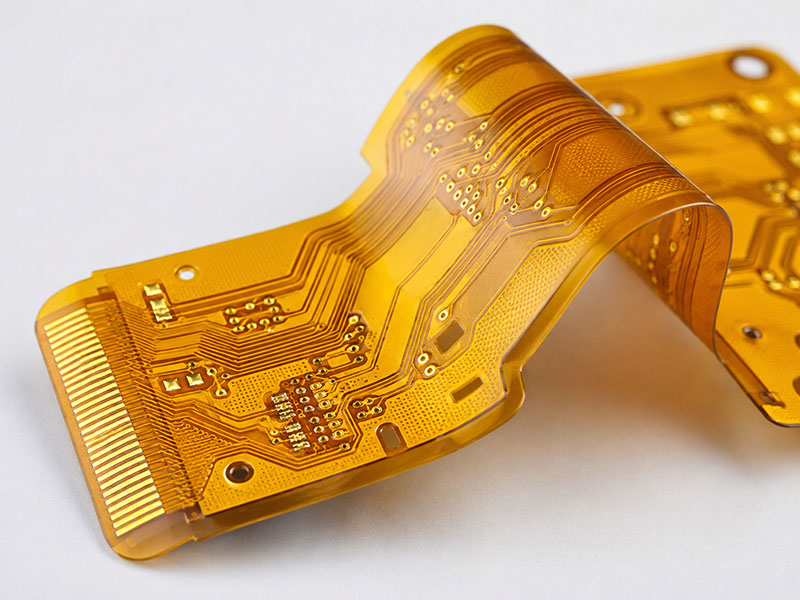
Polyimide offers a glass transition temperature (Tg) above 250°C, compared to 135–170°C for standard FR4. This is not a marginal difference — it changes what the board can survive during lead-free assembly, rework, and service life.
| Property | Polyimide | Standard FR4 |
|---|---|---|
| Glass transition temperature (Tg) | >250°C | 135–170°C |
| Continuous use temperature | Up to 260°C | Up to 130°C |
| Dielectric constant (1 GHz) | 3.4–3.5 | 4.2–4.8 |
| CTE, in-plane (ppm/°C) | 12–16 | 14–17 |
| UL 94 flammability rating | V-0 | V-0 |
Both materials achieve UL 94 V-0. The thermal performance gap is what separates them.
Material Properties That Drive Design Decisions
Polyimide’s thermal stability is the primary reason engineers specify it. During lead-free reflow, peak temperatures typically reach 245–260°C. Standard FR4 can survive one or two passes, but repeated thermal cycles near its Tg accelerate delamination and z-axis stress on plated holes. Polyimide eliminates this risk — its Tg well above 250°C means the board remains dimensionally stable through multiple reflow cycles and high-temperature functional testing.
The dielectric constant of 3.4–3.5 at 1 GHz is lower than FR4’s 4.2–4.8. This improves signal propagation speed and simplifies impedance calculations at moderate frequencies. But above 10 GHz, Rogers or PTFE-based materials remain the better choice. Polyimide’s dielectric advantage over FR4 is real; it is not a substitute for purpose-built RF laminates.
Moisture absorption requires careful grade selection. Values vary significantly across polyimide products and must be evaluated against a specified test condition. DuPont Kapton HN film — the most widely referenced base material — absorbs approximately 2.8% by weight after 24-hour water immersion per ASTM D570. Composite polyimide laminates with modified resin systems, such as Panasonic R-F775, typically fall in the range of 1.3–1.8% under IPC-TM-650 Method 2.6.2. When requesting a material datasheet, confirm both the test method and exposure duration — values reported at 24-hour immersion versus 24-hour humidity exposure can differ by 0.5% or more for the same product.
Absorbed moisture raises the effective dielectric constant and can shift controlled-impedance traces outside tolerance. Boards stored before assembly should be baked at 120°C for 2–4 hours before reflow. This step is frequently skipped and is a documented root cause of impedance drift in flex assemblies.
Rigid vs Flexible Polyimide PCB: Different Problems, Same Base Material
Polyimide is used in two structurally different board types. Which one applies to your design changes your fabrication spec, stack-up, and assembly process.
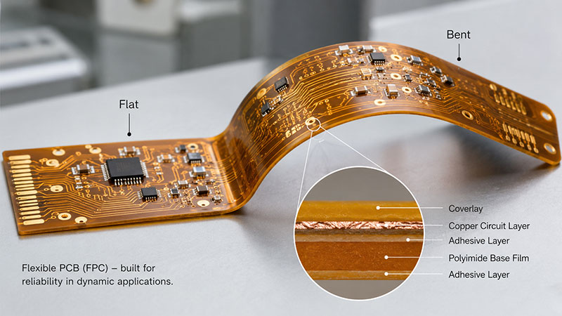
Flexible polyimide PCB (flex PCB) uses thin polyimide film — typically 12.5 μm to 125 μm — as the dielectric. Copper foil is laminated directly to the film, either with an adhesive layer (conventional) or without (adhesiveless). Adhesiveless flex laminates offer better thermal performance and tighter thickness control. The trade-off: adhesiveless laminates cost more and are available from fewer suppliers.
Flex PCBs divide into two categories based on how they bend in service:
- Dynamic flex — the board bends repeatedly during operation (e.g., printer carriage, robotic joint). Design minimum bend radius at ≥10× total laminate thickness.
- Static flex — the board bends once during assembly and stays in position (e.g., folded inside an enclosure). Minimum bend radius can be relaxed to ≥6× thickness.
Rigid polyimide PCB uses PI-based laminate — examples include Arlon 85N and Isola P96 — processed like a standard rigid board but with polyimide resin instead of epoxy. These are specified when temperature or flame resistance requirements rule out FR4, not for flexibility. Drilling and routing generate fine abrasive dust, so fabricators require appropriate extraction — confirm this capability before ordering.
| Type | Typical Thickness | Bend Use | Primary Reason to Specify |
|---|---|---|---|
| Flexible PI (adhesiveless) | 25–125 μm total | Dynamic or static | Thermal performance + flex |
| Flexible PI (adhesive-based) | 50–200 μm total | Static preferred | Lower cost, wider supply base |
| Rigid PI laminate | 0.4–3.2 mm | None | High Tg, flame resistance |
For procurement: rigid polyimide laminates carry a significant price premium over high-Tg FR4. Confirm with your fabricator whether the operating temperature genuinely exceeds what high-Tg FR4 (Tg 170°C) can handle before committing to polyimide.
Medical and High-Reliability Applications
Polyimide flex is the dominant substrate in portable medical electronics — not because any standard mandates it, but because the combination of flexibility, reduced weight, and thermal stability solves real constraints in these devices.
In portable ultrasound transducer assemblies, flex circuits replace rigid board-to-board connectors, reducing mechanical failure points and stack height simultaneously. In infusion pumps and wearable patient monitors, polyimide flex enables routing through tight enclosure geometries while surviving sterilization cycles that expose boards to elevated temperature and humidity.
IPC Class 3 requirements for polyimide flex carry specific fabrication consequences. Under IPC-6013 (qualification and performance specification for flexible printed boards), Class 3 sets a minimum average copper thickness in plated holes of 20 μm, with a minimum at any single point of 18 μm. Class 2, by comparison, allows 15 μm average with a 12 μm minimum. On thin flex substrates — particularly below 50 μm dielectric thickness — achieving consistent copper deposition to Class 3 tolerances requires tighter control over hole preparation, desmear chemistry, and plating bath parameters. Not all flex fabricators can reliably hit these numbers. Verifying this capability before sourcing is not optional for medical programs.
ISO 13485 adds documentation requirements on top of IPC Class 3. Each panel must carry full lot traceability — material certificate, laminate batch number, plating records — because medical device manufacturers must maintain a Device History Record (DHR) that traces back to the substrate material lot. This applies to Class II and Class III medical devices without exception.
IEC 60601-1 isolation requirements may also affect the stack-up. When a polyimide flex circuit spans areas at different potentials, the dielectric thickness must be calculated against the required working voltage and creepage distance, not only for signal integrity.
Outside medical, the same IPC-6013 Class 3 requirements apply in avionics (DO-160 environmental qualification) and in industrial sensing applications where in-field board replacement is not practical.
When to Choose Polyimide Over FR4 — and When Not To
The case for polyimide comes down to three conditions. If none of them apply, FR4 will perform adequately at lower cost and shorter lead time.
| Condition | Recommended Material |
|---|---|
| Multiple lead-free reflow passes (>2) or rework expected | Polyimide |
| Board must flex dynamically or statically in final assembly | Polyimide flex |
| Sustained operating temperature above 130°C | Polyimide (rigid or flex) |
| RF/microwave above 10 GHz | Rogers or PTFE laminate |
| Standard conditions, cost-sensitive design | FR4 (standard or high-Tg) |
Cost and lead time implications are concrete. Polyimide laminates cost roughly 3–5× more than standard FR4 per panel. Flex fabrication adds process steps — coverlay lamination, stiffener attachment, laser cutting — that rigid FR4 does not require. Prototype lead times for polyimide flex are typically 10–15 days from a specialist flex fabricator, versus 5–7 days for rigid FR4.
One common specification error: requesting polyimide when the real requirement is high-Tg FR4. If the board will see 2–3 lead-free reflow passes but no sustained elevated temperature in service, high-Tg FR4 (Tg 170°C) is sufficient and meaningfully cheaper. Specify polyimide when the thermal or mechanical demand genuinely exceeds what high-Tg FR4 can handle — not as a default performance upgrade.
Summary
Polyimide PCB is not a universal upgrade over FR4 — it is a material chosen to solve specific problems. It performs where FR4 cannot: repeated lead-free reflow cycles, circuits that must flex in service, sustained high operating temperatures, and assembly environments with strict reliability requirements such as medical devices under IPC Class 3 and ISO 13485.
The three questions worth answering before specifying polyimide: Does the board need to flex? Will it face more than two reflow passes or sustained heat above 130°C? Does the application require documentation and traceability beyond standard commercial PCB practice? If the answer to all three is no, high-Tg FR4 is likely sufficient — and meaningfully cheaper. If any condition applies, polyimide is the more defensible choice.