
Rogers PCB materials solve a specific signal integrity problem that FR4 cannot. When operating frequency, insertion loss budget, or impedance tolerance push beyond what standard laminates can reliably deliver, Rogers laminates become the practical choice. This guide explains which material family fits which application, what fabrication capabilities to verify, and what to include in an RFQ.
What Is a Rogers PCB and When Is FR4 No Longer Enough?
Rogers PCB refers to printed circuit boards built using laminates manufactured by Rogers Corporation — a material system, not a specific board format or layer count. The core distinction from FR4 is electrical: Rogers laminates offer tighter dielectric constant (Dk) tolerances, lower dissipation factors (Df), and more stable electrical properties across frequency and temperature.
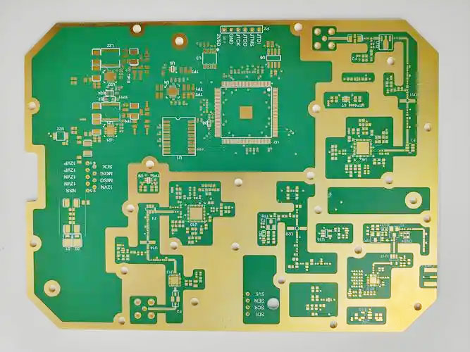
FR4 has a Dk range of approximately 4.2–4.8 and a Df of 0.020–0.025 at 1 GHz. Rogers RO4003C has a nominal Dk of 3.55 ±0.05 and a Df of 0.0027 at 10 GHz. At higher frequencies, that difference in Df directly determines how much signal is lost before it reaches the antenna or connector.
Frequency alone is not the right selection trigger. A design at 2.4 GHz with short traces and relaxed impedance requirements may perform adequately on low-loss FR4. Evaluate all of the following before committing to Rogers:
- Total insertion loss budget across the signal path
- Required impedance tolerance (±5% vs ±10%)
- Phase stability requirements across the operating temperature range
- Board cost target and production volume
Low-loss FR4 variants such as Isola 370HR or Panasonic Megtron 6 occupy the middle ground. They cost less than Rogers and process like standard FR4, but cannot match Rogers materials above 5–6 GHz or in phase-critical designs. Confirm whether high-performance FR4 closes the loss budget before specifying Rogers.
| Material | Dk (nominal) | Df at 10 GHz | Typical Use Case |
|---|---|---|---|
| Standard FR4 | 4.2–4.8 | 0.020–0.025 | Digital, low-frequency analog |
| High-performance FR4 | 3.5–4.0 | 0.006–0.012 | High-speed digital, moderate RF |
| Rogers RO4003C | 3.55 ±0.05 | 0.0027 | Commercial RF, microwave |
| Rogers RT/duroid 5880 | 2.20 ±0.02 | 0.0009 | Satellite, mmWave |
Rogers PCB Material Families and Stackup Options
The Rogers laminate family you choose determines not just electrical performance, but also fabrication complexity and cost. Three families cover most commercial and defense RF applications.
RO4000 Series
RO4003C and RO4350B are the most widely used commercial RF laminates. Both are ceramic-filled hydrocarbon laminates — not PTFE — which means they can be drilled and laminated on standard FR4 equipment with process modifications. This makes them more available and less expensive to fabricate than PTFE-based materials. RO4003C (Dk 3.55) and RO4350B (Dk 3.48) are electrically similar; RO4350B carries UL 94 V-0 flame rating, which some markets require.
RT/duroid Series
RT/duroid 5880 and 5870 are PTFE/glass composites with among the lowest Df values available in commercial PCB laminates — 0.0009 at 10 GHz for RT/duroid 5880. That performance comes with fabrication complexity: PTFE requires plasma treatment before lamination for copper adhesion, controlled drilling to prevent burring, and is prone to dimensional change under thermal stress. Fewer fabricators can handle it reliably. The cost premium over RO4003C is significant.
Other Ceramic-Filled Laminates
Rogers RO3003, RO3006, and RO3010 cover a Dk range from 3.0 to 10.2. Higher-Dk materials allow more compact antenna dimensions at a given resonant frequency, which is why RO3006 (Dk 6.15) appears in space-constrained microstrip patch designs.
Full Rogers vs Hybrid Stackup
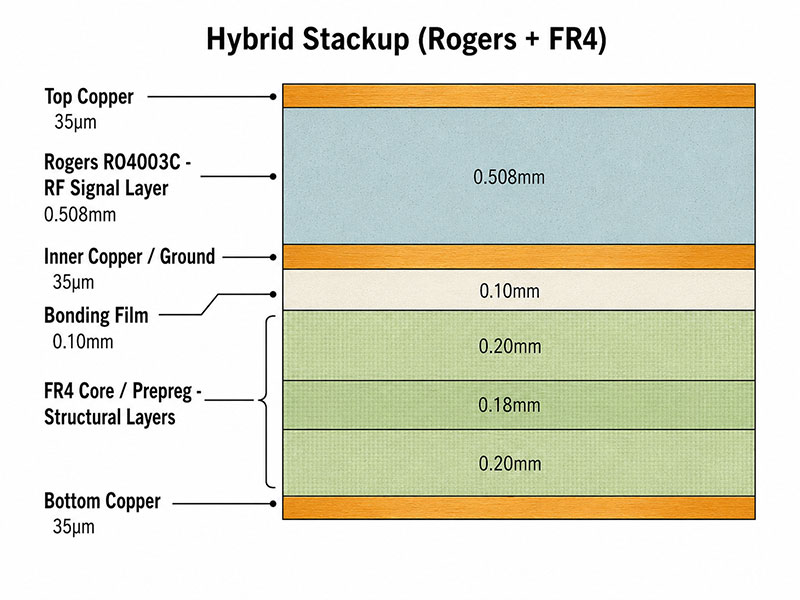
A full Rogers multilayer uses Rogers laminate for all core and prepreg layers. A hybrid stackup uses Rogers only on the critical RF layers, with FR4 on the remaining structural layers. Hybrid construction reduces cost significantly — often 40–60% on a 6–8 layer board — but introduces CTE mismatch between Rogers and FR4 that requires compatible bonding film and controlled lamination. Not all fabricators support hybrid lamination reliably; confirm capability before design.
| Full Rogers | Rogers + FR4 Hybrid | |
|---|---|---|
| Cost | Higher | 40–60% less on multilayer |
| Signal layers | All Rogers | Rogers on RF layers only |
| CTE mismatch risk | Low | Present — requires compatible bonding film |
| Fabrication complexity | High | Higher (dual-material lamination) |
| Common applications | Aerospace, satellite, test fixtures | Commercial RF, antenna modules |
Electrical Properties That Matter: Dk, Df, Thickness, and Copper Roughness
Four properties determine whether a Rogers laminate meets your design’s electrical requirements. Reading a datasheet without understanding the test conditions behind each value leads to poor material comparisons.
Dielectric Constant (Dk)
Dk determines transmission line impedance, signal propagation velocity, and antenna resonant dimensions. The design Dk used in impedance calculators may differ from the value printed in the datasheet, which is typically measured at a specific frequency using the IPC-TM-650 method or Bereskin cavity resonance. For Rogers RO4003C, the datasheet Dk of 3.55 is measured at 10 GHz; the value at lower frequencies is slightly higher. Use the Rogers MWI-2000 calculator or a field solver that accounts for frequency-dependent Dk.
Dissipation Factor (Df)
Df defines dielectric loss — energy absorbed per unit length of transmission line. At 10 GHz, standard FR4 at Df 0.020 can add 3–5 dB of insertion loss per inch of trace; RO4003C at Df 0.0027 adds under 1 dB over the same length. That difference becomes the limiting constraint in 5G antenna feeds, radar IF chains, and mmWave front-end boards. When comparing Df values across datasheets, confirm the test frequency — values measured at 1 GHz are not equivalent to values at 10 GHz, because Df increases with frequency.
Dielectric Thickness Tolerance
Controlled impedance depends directly on core thickness. Rogers RO4003C cores carry ±5% thickness tolerance; standard FR4 cores typically run ±10%. Tighter tolerance reduces as-built impedance variation and the number of traces that fall outside specification after fabrication. TDR coupon testing remains good practice regardless.
Copper Roughness
Above 5 GHz, the skin effect confines current to the conductor surface. Copper roughness increases the effective path length and raises conductor loss. Standard electrolytic copper (Ra ≈ 2–3 µm) causes measurable insertion loss degradation at 10 GHz. Low-profile copper (Ra < 1 µm) and rolled annealed copper reduce this. Rogers datasheets specify which copper type is available and which was used during characterization — a detail that matters when your impedance model assumes smooth copper.
| Property | What It Affects | Key Specification |
|---|---|---|
| Dk | Impedance, signal velocity, antenna size | Nominal + test frequency + tolerance |
| Df | Insertion loss per unit length | Value at operating frequency + test method |
| Core thickness | Impedance repeatability | ±5% (Rogers RO4003C) vs ±10% (FR4) |
| Copper roughness | Conductor loss above 5 GHz | Ra (µm); low-profile < 1 µm |
Rogers PCB Applications and the Material Requirements Behind Them
Rogers PCB is not a default upgrade from FR4. The cost premium is justified when the application carries specific electrical requirements that FR4 cannot reliably meet.
5G Antenna and RF Front-End Modules
5G sub-6 GHz antenna arrays and mmWave patch antenna modules require stable Dk across temperature and humidity. Antenna resonant frequency shifts directly with Dk variation — a ±0.05 change in Dk at 28 GHz produces a measurable frequency shift and pattern distortion. RO4003C and RO4350B are common here because their Dk stability over −40°C to +85°C is well-characterized and tight enough for commercial antenna design.
Radar Sensor PCBs
77 GHz automotive radar boards require low dielectric loss, consistent phase between antenna elements, and dimensional stability across temperature cycling. These requirements typically point to PTFE-based laminates (RT/duroid 5880) or ceramic-filled materials with Df below 0.002. Thermal cycling changes element spacing, so CTE and dimensional stability matter alongside electrical performance.
Satellite and Aerospace Communication
LEO satellite downlinks and aerospace communication systems combine high-frequency operation with wide temperature excursions and extended service life. These applications require full Rogers stackups, material traceability per lot, and fabrication conforming to AS9100 or equivalent quality standards. RT/duroid 5880 is common in this segment.
High-Frequency Test Fixtures
RF test fixtures require predictable impedance and minimal fixture-induced insertion loss — inconsistency corrupts the device measurements they support. Rogers laminates are standard in fixture fabrication because their stable dielectric properties allow fixtures to be characterized and de-embedded with confidence.
Where Rogers Is Not the Right Choice
Standard Bluetooth designs, 2.4 GHz IoT modules, and low-cost RFID readers typically perform adequately on high-performance FR4. Short trace lengths at 2.4 GHz do not generate enough insertion loss to justify Rogers PCB cost. Confirm the insertion loss budget against actual trace length and line width before specifying Rogers.
| Application | Key Material Requirement | Typical Rogers Material |
|---|---|---|
| 5G sub-6 GHz antenna | Stable Dk, Df < 0.004 | RO4003C, RO4350B |
| 77 GHz automotive radar | Df < 0.002, phase consistency | RT/duroid 5880, RO3003 |
| Satellite communication | Low loss, traceability, temperature stability | RT/duroid 5880, RO4003C |
| RF test fixtures | Predictable impedance, low loss | RO4003C |
| High-speed interconnect | Low loss, controlled impedance | RO4350B, hybrid stackup |
Rogers PCB Fabrication: Why It Is Not Processed Like Standard FR4
Rogers PCB fabrication requires material-specific handling at every process stage. Sending a Rogers design to a fabricator with only standard FR4 experience is a direct quality risk.
Material Verification
Before cutting begins, the laminate should be verified against the purchase order: material grade, copper type, core thickness, and lot number. In aerospace and defense applications, a certificate of conformance (CoC) per material lot is required for traceability. Substituting a similar-specification laminate without written approval compromises the design and may violate contractual requirements. Require a documented no-substitution policy before placing the order.
Drilling PTFE Materials
PTFE-based laminates such as RT/duroid 5880 require lower feed rates, higher spindle speeds, and carbide drill bits designed for soft materials — not the parameters used for FR4. Without correct settings, PTFE smears, burrs form at the hole wall, and delamination risk increases. Hole-wall quality in PTFE directly affects plated-through hole reliability under thermal cycling.
Copper Adhesion on PTFE
Before multilayer lamination, PTFE layers require plasma treatment or chemical etching to raise surface energy and ensure proper copper bonding. Skipping this step leads to delamination under thermal stress. This process step requires equipment and training that general FR4 shops typically lack.
Hybrid Lamination
Rogers + FR4 hybrid stackups require bonding films compatible with both dielectrics. RO4003C has an in-plane CTE of approximately 17 ppm/°C, close to copper; mixing it with FR4 still requires controlled lamination pressure and temperature profiling. Warpage and misregistration between Rogers and FR4 layers are documented failure modes when fabricators lack hybrid lamination experience.
Controlled Impedance Verification
After fabrication, controlled impedance traces should be tested using a time-domain reflectometer (TDR) on coupon traces built into the panel. The target tolerance on Rogers materials is typically ±5% for microstrip and stripline. Request the TDR data as a deliverable, not just a pass/fail statement.
Surface Finish Selection
ENIG (electroless nickel immersion gold) is the standard surface finish on Rogers PCBs — flat, solderable, compatible with the material. Immersion silver is used where skin-effect conductor losses at the surface matter, as silver has higher conductivity than nickel. HASL is generally avoided; the uneven surface height introduces impedance variation on controlled-impedance traces.
| Fabrication Stage | Rogers-Specific Risk | Mitigation |
|---|---|---|
| Drilling (PTFE) | Smear, burr, hole-wall damage | PTFE-optimized drill parameters |
| Copper adhesion (PTFE) | Delamination under thermal stress | Plasma treatment before lamination |
| Hybrid lamination | CTE mismatch, warpage, misregistration | Compatible bonding film, controlled profile |
| Impedance verification | Out-of-spec traces not detected | TDR coupon test with report |
| Surface finish | Impedance variation (HASL) | Specify ENIG or immersion silver |
Rogers PCB Cost, Supplier Selection, and RFQ Specification
Rogers PCB costs 2–5× more than a comparable FR4 board, depending on material grade, stackup type, and quantity. Understanding what drives cost makes it easier to control it and evaluate whether a quote reflects the actual specification.
What Drives Cost
- Material grade: RT/duroid 5880 costs significantly more than RO4003C. Lower Df comes at a price.
- Stackup choice: Full Rogers vs hybrid — hybrid cuts cost by using FR4 on non-RF layers.
- Core thickness and copper type: Non-standard thicknesses and low-profile copper are not stocked items; they require custom material orders with longer lead times.
- Layer count and controlled impedance layers: More controlled impedance layers increase test requirements and fabrication time.
- Prototype quantity: Rogers laminate is expensive at prototype panel utilization rates. A 2-layer prototype that occupies 10% of a panel still pays for the full panel.
Cost-Control Methods
Use Rogers laminate only on layers that carry RF signals; build structural and digital layers in FR4. Choose core thicknesses that your fabricator stocks — confirm availability before locking the stackup design. Validate the impedance model with the fabricator before layout is complete. Last-minute stackup changes due to unavailable material are a common source of cost escalation and schedule delay on Rogers PCB orders.
Supplier Qualification
Not all PCB fabricators support Rogers PCB reliably. Before sending an RFQ, confirm:
- Experience fabricating the specific Rogers material family in your stackup
- PTFE processing capability (plasma treatment, PTFE-specific drill parameters) if RT/duroid is in the design
- Hybrid lamination capability for Rogers + FR4 constructions
- Material traceability documentation — CoC per lot, not batch
- Controlled impedance modeling and TDR coupon testing as standard deliverables
- Microsection inspection capability and willingness to provide cross-section reports
- Written no-substitution policy — unapproved material substitution should be contractually prohibited
RFQ Specification Checklist
An incomplete RFQ produces quotes that cannot be compared and orders that may arrive with substituted materials. Include all of the following:
| RFQ Item | Required Detail |
|---|---|
| Rogers material grade | Exact part number (e.g., RO4003C LoPro 0.508 mm) |
| Dk and Df basis | Datasheet revision, test frequency |
| Core thickness | Nominal + tolerance |
| Copper weight and type | e.g., 1 oz low-profile copper |
| Finished board thickness | Nominal + tolerance |
| Stackup | Full Rogers or hybrid; stackup approval required before production |
| Impedance targets | Trace reference, nominal Ω, tolerance (e.g., 50 Ω ±5%) |
| Surface finish | ENIG or immersion silver |
| Substitution rules | No substitution without written approval |
| Certification | CoC, IPC Class 2/3, AS9100 if applicable |
| Quantity | Prototype or production |
A Rogers PCB quote without a confirmed stackup and approved material specification is not a reliable cost estimate. Require stackup approval as a gate before production release.
Summary
The decision to use Rogers PCB starts with the insertion loss budget, not operating frequency alone. If the signal path cannot tolerate the loss FR4 introduces at the operating frequency, trace length, and impedance target, Rogers materials close that gap. Choose the material family based on Dk, Df at operating frequency, fabrication complexity, and cost — not on the Rogers name. Hybrid stackups reduce cost where full Rogers is not necessary. Fabricator capability matters as much as material selection: a shop with PTFE processing experience, hybrid lamination capability, and TDR testing will outperform a general fabricator using the same laminate. Specify the exact material grade, copper type, stackup, and impedance targets in the RFQ. A vague specification produces quotes you cannot compare.