Lead-free soldering has been the industry standard for nearly two decades. Since the RoHS directive reshaped electronics manufacturing, SAC305 has become the dominant solder alloy, and engineers worldwide have adapted their processes accordingly. Most of them kept using FR4.
And for many applications, that works fine.
Standard FR4 is not universally incompatible with lead-free assembly. Millions of consumer electronics boards ship every year using conventional FR4 laminates processed through lead-free reflow lines. The material is well-understood, widely available, and cost-effective.
But there is a category of failures — delamination, blistering, via cracking, warping — that occurs specifically at the intersection of lower-grade FR4 and high-stress lead-free conditions. Understanding where that boundary sits, and what drives failures across it, is what separates a reliable design from a field return waiting to happen.
The core issue is not that standard FR4 fails in lead-free assembly. The issue is that reliability margins shrink significantly under high thermal stress, multiple reflow cycles, or moisture-sensitive conditions — and for many designs, those conditions are not exceptional. They are the default.
内容
- The Temperature Reality: SAC305 Demands More Than Tin-Lead Ever Did
- What Tg Actually Means — And What It Does Not
- The Failure Modes: What High Thermal Stress Does to FR4
- The Multiple Reflow Problem: Cumulative Stress, Not Single Events
- The Specification Gap: Why “FR4” on the BOM Is Not Enough
- Choosing the Right Laminate: A Practical Framewor
- Process-Side Mitigations: Useful, But Not a Substitute
- Conclusion: Standard FR4 Is Not the Enemy — Mismatched Specifications Are
The Temperature Reality: SAC305 Demands More Than Tin-Lead Ever Did
To understand why FR4 grade selection matters more under lead-free conditions, start with the temperature profile.
Tin-lead solder (Sn63Pb37) has a melting point of 183°C. Typical reflow peak temperatures for tin-lead processes sat around 205–215°C, with relatively short time above liquidus.
SAC305 (96.5% tin, 3% silver, 0.5% copper) has a liquidus temperature of 217°C. To achieve reliable wetting and intermetallic formation across all joint geometries on a board, reflow profiles typically run peak temperatures of 245–260°C, with 30–60 seconds above liquidus.
That is a 30–45°C increase in peak temperature compared to tin-lead — sustained, repeated, and applied uniformly across the entire laminate every time the board passes through the oven.
The laminate does not get a pass just because the solder joints are the primary target.
What Tg Actually Means — And What It Does Not
Glass transition temperature (Tg) is one of the most cited laminate parameters in lead-free discussions, and also one of the most commonly misunderstood.
Tg is the temperature at which a thermoset resin transitions from a rigid, glassy state to a softer, rubbery state. Below Tg, the resin is relatively stiff and its coefficient of thermal expansion (CTE) is low and predictable. Above Tg, modulus drops sharply and the CTE — particularly in the z-axis — increases dramatically.
Exceeding Tg does not immediately damage the laminate. The material does not melt, crack, or decompose at Tg. What changes is its mechanical behavior and thermal expansion characteristics, making it far more vulnerable to stress-induced failures during the reflow event.
Standard FR4 is typically specified at Tg 130°C. Some grades reach Tg 140°C. Either way, a SAC305 reflow profile at 245–260°C peak means the laminate spends a meaningful portion of every reflow cycle well above its glass transition point — in a state where z-axis expansion is elevated and interlaminar bond strength is at its lowest.
For a single, low-layer-count, thin-copper board with no dense via fields and no BGA components, this may not cause observable failure. The stress is real, but the design has enough margin to absorb it.
For a dense multilayer board with heavy copper, closely-spaced PTH vias, and BGA devices — processed twice for double-sided assembly and potentially again for rework — the same material condition is a different story.
Td and T288: The Metrics That Actually Predict Multi-Reflow Reliability
Beyond Tg, two parameters more directly predict laminate survival under repeated high-temperature exposure: thermal decomposition temperature (Td) and T288 time to delamination.
Td is the temperature at which the laminate resin begins to permanently decompose — measured as the point where the sample loses a defined percentage of its original mass under controlled heating. For many standard FR4 grades, Td falls in the range of 300–330°C.
Normal reflow peak temperatures of 245–260°C do not reach Td. But that does not mean the resin is unaffected. Repeated exposure to high reflow temperatures accelerates resin degradation and interfacial fatigue, especially in lower-Td laminates — even when peak temperatures remain below Td itself. Each cycle incrementally consumes the material’s thermal endurance budget.
T288 measures how long a laminate can withstand 288°C before delamination occurs. It is a direct indicator of interlaminar bond durability under thermal stress — essentially asking: how much thermal punishment can this laminate absorb before the layers separate?
Lower-grade FR4 laminates may exhibit significantly shorter T288 performance compared to high-Tg materials. Always request and compare supplier datasheets rather than relying on generic “FR4” classifications. The variance between laminate families from different manufacturers is substantial, and the difference matters in any design with more than one or two reflow cycles.
The Failure Modes: What High Thermal Stress Does to FR4
When the conditions are wrong — wrong laminate grade for the thermal load, wrong process parameters, wrong moisture control — FR4 fails in predictable ways.
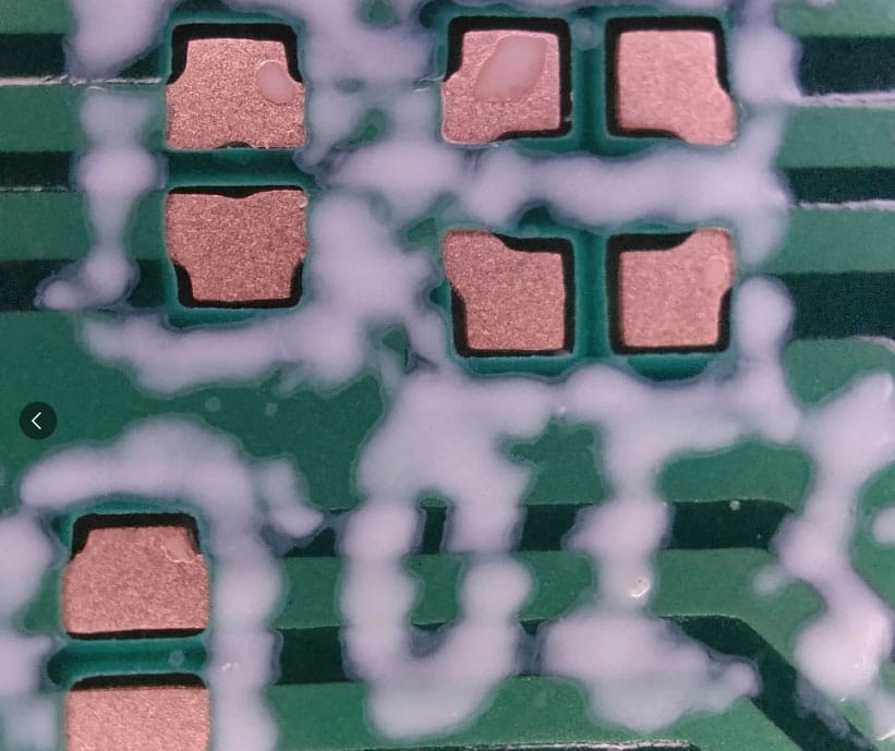
Delamination
Delamination is the separation of laminate layers at the resin-glass or resin-copper interface. It is the most direct consequence of z-axis CTE mismatch under thermal stress.
Above Tg, the resin expands in the z-axis at a rate significantly higher than the copper foil and glass fiber it is bonded to. The differential strain generates peel stress at the interface. In a single reflow cycle on a new, dry board, this may be manageable. Across multiple cycles on a laminate with already degraded interfacial adhesion, it is not.
High-risk configurations include: multilayer boards (more interfaces to fail), heavy copper (more constraint, more stress), high via density (stress concentration), and double-sided assembly (guaranteed minimum two full cycles).
Blistering and the Popcorn Effect
Standard FR4 absorbs moisture. This is not a flaw — it is a property of epoxy-based thermoset systems. Under normal storage conditions, the absorbed moisture is distributed through the laminate matrix and causes no problems.
During reflow, that changes. As the board temperature rises, absorbed moisture converts rapidly to steam. The vapor pressure generated can exceed the interlaminar bond strength, causing localized delamination — visible as blisters on the surface or internal voids detectable by cross-section.
This failure mode is strongly influenced by pre-assembly handling. Boards stored in humid environments without moisture barrier packaging, or held in production queues for extended periods, accumulate enough moisture to make blistering likely regardless of laminate grade. The combination of moisture-loaded standard FR4 and SAC305 reflow temperatures is one of the more reliable ways to produce scrap.
Warping
Above Tg, the resin’s modulus drops sharply. A board that was flat and rigid at room temperature becomes significantly more compliant when heated to reflow temperatures. Non-uniform heating across the panel — inherent in any continuous reflow oven — creates differential thermal gradients that translate into bending moments.
If the board returns to ambient while still deformed, the reduced modulus allows the deformation to partially set as a permanent condition. This is warping.
For BGA devices, even modest warping at the component mounting level destroys the coplanarity assumptions that reliable solder joint formation depends on. The result is opens on corner balls, shorts on inner balls, or — worse — joints that appear acceptable on X-ray but carry undetected voids and reduced fatigue life.
Via Barrel Cracking
Plated-through hole (PTH) vias are structurally vulnerable under z-axis thermal expansion. The copper barrel is bonded to laminate material on all sides. When the laminate expands in the z-axis above Tg, the barrel is stretched axially. When the board cools and the laminate contracts, the barrel is compressed. Repeat this enough times, and the copper barrel develops fatigue cracks — typically at the knee of the via where stress concentration is highest.
The dangerous aspect of via barrel cracking is its latency. The cracks may be below the resolution of standard AOI and may not produce a measurable resistance change until the crack propagates fully through the barrel cross-section. Boards that pass electrical test at the end of assembly can fail in the field after a relatively small number of thermal cycles.
High-Tg laminates with lower z-axis CTE above Tg substantially reduce the expansion differential driving this failure mechanism.
The Multiple Reflow Problem: Cumulative Stress, Not Single Events
Double-sided SMT assembly means every board passes through the reflow oven at least twice. Add rework — BGA reballing, component replacement, inspection-triggered touch-up — and a board may see four to six full thermal cycles before it ships.
Each cycle is not an independent event. Resin degradation, interfacial fatigue, and copper barrel work-hardening are cumulative. A laminate that survives the first cycle with measurable margin may have significantly less margin entering the second and third.
The answer to “how many reflow cycles can standard FR4 survive” depends heavily on laminate grade, board construction, and process parameters. In high-stress configurations — dense multilayer, heavy copper, BGA population, double-sided assembly — standard FR4 reliability can degrade after as few as two full reflow cycles.
The specific variables that compound risk include: board thickness and layer count (more material, more cumulative expansion), copper weight per layer (heavier copper constrains differently), peak reflow temperature and time above liquidus, pre-reflow moisture content, via density and aspect ratio, and whether BGA or other area-array devices are present.
None of these variables alone determines the outcome. The combination does.
The Specification Gap: Why “FR4” on the BOM Is Not Enough
Here is where many reliability problems originate: the design engineer specifies “FR4,” the procurement team sources the lowest-cost laminate that matches, and the resulting board has properties that were never evaluated against the actual thermal load.
IPC-4101 defines laminate performance classes through slash sheets — specification designators such as /21, /24, and /26 that define different performance tiers, including variations in Tg, Td, and thermal reliability requirements. Specifying only “FR4” does not reference any of these tiers. It does not guarantee a minimum Tg, a minimum Td, or a minimum T288.
Different manufacturers also use proprietary internal designations that may or may not align cleanly with IPC slash sheet boundaries. Two laminates that both pass incoming inspection as “FR4” can have meaningfully different thermal performance profiles.
The specification on an engineering document should define the actual performance requirements: minimum Tg, minimum Td, minimum T288 value, tested per the relevant IPC methods. If the design requires a particular thermal margin, that margin needs to be specified — not assumed from a generic material category label.
Choosing the Right Laminate: A Practical Framewor
Upgrading from standard FR4 does not require moving to exotic materials. For most lead-free reliability improvements, high-Tg FR4 is the practical first step.
High-Tg FR4 (Tg 150–170°C) uses a modified epoxy resin system that raises the glass transition point, reduces z-axis CTE, and typically improves Td and T288 performance as well. The processing characteristics are nearly identical to standard FR4, and the cost premium is modest. Representative materials include Shengyi S1000-2 and Isola 370HR, both of which are widely available and have established track records in lead-free assembly.
| Application Profile | Recommended Material | Key Specification Targets |
|---|---|---|
| Single/simple double-sided, consumer electronics | High-Tg FR4 (Tg ≥ 150°C) | Td ≥ 325°C, T288 per datasheet |
| Multilayer, industrial, heavy copper, BGA | High-Tg FR4 / Mid-loss laminate | Tg ≥ 170°C, Td ≥ 340°C |
| High thermal reliability, automotive, aerospace | Polyimide-based laminate | Per IPC-4101 /40 series or equivalent |
| High-frequency RF / millimeter-wave designs | Rogers / PTFE-based laminate | Dk/Df primary; thermal reliability evaluated separately |
Note that polyimide and Rogers/PTFE laminates address fundamentally different requirements. Polyimide is selected for thermal robustness. Rogers and PTFE-based materials are selected for controlled dielectric properties at high frequencies. These are not interchangeable, and automotive multilayer designs rarely require RF-grade materials.
Process-Side Mitigations: Useful, But Not a Substitute
Process controls can reduce risk on standard FR4, but they cannot eliminate the underlying thermal margin deficit of a laminate that is not rated for the load.
Pre-bake before reflow — typically 125°C for 4–8 hours — drives absorbed moisture out of the laminate before it can vaporize during reflow. This substantially reduces blistering risk and is good practice regardless of laminate grade. Boards stored without moisture barrier packaging for more than 24–48 hours in humid environments should be baked before processing.
Reflow profile optimization — minimizing time above liquidus, controlling ramp rates, reducing peak temperature where solder joint quality allows — reduces cumulative thermal stress per cycle. A profile that achieves equivalent wetting at 248°C rather than 258°C represents measurable margin improvement.
These measures are worth implementing. They are not, however, equivalent to specifying a laminate with appropriate Tg, Td, and T288 for the thermal load. A moisture-controlled, optimized-profile reflow process on inadequate laminate still has inadequate laminate.
Conclusion: Standard FR4 Is Not the Enemy — Mismatched Specifications Are
Standard FR4 is not incompatible with lead-free assembly. It is a well-characterized, cost-effective material that continues to serve appropriately specified applications effectively.
The reliability risk emerges when the thermal demands of the assembly process — SAC305 reflow temperatures, multiple reflow cycles, moisture exposure, dense via structures — exceed the thermal margin that a given laminate grade can reliably sustain. That mismatch is preventable, and prevention starts at the specification stage.
The three failure mechanisms to hold in mind: insufficient Tg drives elevated z-axis CTE, generating delamination and warping stress; insufficient Td and T288 allow interfacial fatigue to accumulate under repeated thermal exposure; inadequate moisture control enables the popcorn effect to destroy interlaminar bonds before the solder joint is ever formed.
Engineering checklist before committing to a laminate grade:
- Confirm laminate Tg ≥ 150°C as a baseline for any lead-free process
- Reference IPC-4101 slash sheet in procurement documentation and specify minimum Tg and Td values explicitly
- Request T288 test data from the laminate supplier and compare across candidates
- Count actual expected reflow cycles, including rework scenarios, before finalizing material selection
- For high via density, heavy copper, or BGA-populated designs, increase laminate grade requirements accordingly
- Implement pre-bake protocol as standard practice, not an exception procedure
The question is not whether standard FR4 can survive lead-free soldering. For low-complexity designs under controlled conditions, many grades can. The question is whether the specific laminate being purchased, under the specific thermal load of the specific assembly process, has enough margin that field reliability is not dependent on everything going exactly right.